A Quick Overview of MSAA
Previous article in the series: Applying Sampling Theory to Real-Time Graphics
Updated 1/27/2016 - replaced the MSAA partial coverage image with a new image that illustrates subsamples being written to, as suggested by Simon Trümpler.
MSAA can be a bit complicated, due to the fact that it affects nearly the entire rasterization pipeline used in GPU’s. It’s also complicated because really understanding why it works requires at least a basic understanding of signal processing and image resampling. With that in mind I wanted to provide an quick overview of how MSAA works on a GPU, in order to provide the some background material for the following article where we’ll experiment with MSAA resolves. Like the previous article on signal processing, feel free to skip if you’re already an expert. Or better yet, read through it and correct my mistakes!
Rasterization Basics
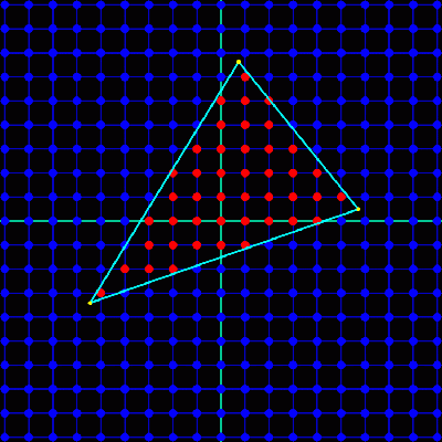
A modern D3D11-capable GPU features hardware-supported rendering of point, line, and triangle primitives through rasterization. The rasterization pipeline on a GPU takes as input the vertices of the primitive being rendered, with vertex positions provided in the homogeneous clip space produced by transformation by some projection matrix. These positions are used to determine the set of pixels in the current render target where the triangle will be visible. This visible set is determined from two things: coverage, and occlusion. Coverage is determined by performing some test to determine if the primitive overlaps a given pixel. In GPU’s, coverage is calculated by testing if the primitive overlaps a single sample point located in the exact center of each pixel 1. The following image demonstrates this process for a single triangle:
Occlusion tells us whether a pixel covered by a primitive is also covered by any other triangles, and is handled by z-buffering in GPU’s. A z-buffer, or depth buffer, stores the depth of the closest primitive relative to the camera at each pixel location. When a primitive is rasterized, its interpolated depth is compared against the value in the depth buffer to determine whether or not the pixel is occluded. If the depth test succeeds, the appropriate pixel in the depth buffer is updated with new closest depth. One thing to note about the depth test is that while it is often shown as occurring after pixel shading, almost all modern hardware can execute some form of the depth test before shading occurs. This is done as an optimization, so that occluded pixels can skip pixel shading. GPU’s still support performing the depth test after pixel shading in order to handle certain cases where an early depth test would produce incorrect results. One such case is where the pixel shader manually specifies a depth value, since the depth of the primitive isn’t known until the pixel shader runs.
Together, coverage and occlusion tells us the visibility of a primitive. Since visibility can be defined as 2D function of X and Y, we can treat it as a signal and define its behavior in terms of concepts from signal processing. For instance, since coverage and depth testing is performed at each pixel location in the render target the visibility sampling rate is determined by the X and Y resolution of that render target. We should also note that triangles and lines will inherently have discontinuities, which means that the signal is not bandlimited and thus no sampling rate will be adequate to avoid aliasing in the general case.
Oversampling and Supersampling
While it’s generally impossible to completely avoid aliasing of an arbitrary signal with infinite frequency, we can still reduce the appearance of aliasing artifacts through a process known as oversampling. Oversampling is the process of sampling a signal at some rate that’s higher than our intended final output, and then reconstructing and resampling the signal again at the output sample rate. As you’ll recall from the first article, sampling at a higher rate causes the clones of a signal’s spectrum to be further apart. This results in less of the higher-frequency components leaking into the reconstructed version of the signal, which in the case of an image means a reduction in the appearance of aliasing artifacts.
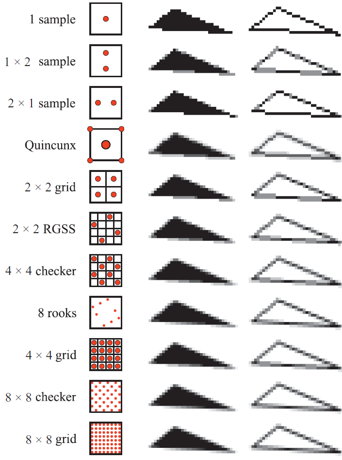
When applied to graphics and 2D images we call this supersampling, often abbreviated as SSAA. Implementing it in a 3D rasterizer is trivial: render to some resolution higher than the screen, and then downsample to screen resolution using a reconstruction filter. The following image shows the results of various supersampling patterns applied to a rasterized triangle:
The simplicity and effectiveness of supersampling resulted in it being offered as a driver option for many early GPU’s. The problem, however, is performance. When the resolution of the render target is increased, the sampling rate of visibility increases. However since the execution of the pixel shader is also tied to the resolution of the pixels, the pixel shading rate would also increase. This meant that any work performed in the pixel shader, such as lighting or texture fetches, would be performed at a higher rate and thus consume more resources. The same goes for bandwidth used when writing the results of the pixel shader to the render target, since the write (and blending, if enabled) is performed for each pixel. Memory consumption is also increased, since the render target and corresponding z buffer must be larger in size. Because of these adverse performance characteristics, supersampling was mostly relegated to a high-end feature for GPU’s with spare cycles to burn.
Supersampling Evolves into MSAA
So we’ve established that supersampling works in principle for reducing aliasing in 3D graphics, but that it’s also prohibitively expensive. In order to keep most of the benefit of supersampling without breaking the bank in terms of performance, we can observe that aliasing of triangle visibility function (AKA geometric aliasing) only occurs at the edges of rasterized triangles. If we hopped into a time machine and traveled back to 2001, we would also observe that pixel shading mostly consists of texture fetches and thus doesn’t suffer from aliasing (due to mipmaps). These observations would lead us to conclude that geometric aliasing is the primary form of aliasing for games, and should be our main focus. This conclusion is what what caused MSAA to be born.
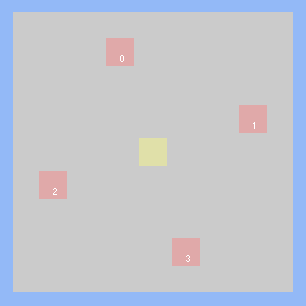
In terms of rasterization, MSAA works in a similar manner to supersampling. The coverage and occlusion tests are both performed at higher-than-normal resolution, which is typically 2x through 8x. For coverage, the hardware implements this by having N sample points within a pixel, where N is the multisample rate. These samples are known as subsamples, since they are sub-pixel samples. The following image shows the subsample placement for a typical 4x MSAA rotated grid pattern:
The triangle is tested for coverage at each of the N sample points, essentially building a bitwise coverage mask representing the portion of the pixel covered by a triangle 2. For occlusion testing, the triangle depth is interpolated at each covered sample point and tested against the depth value in the z buffer. Since the depth test is performed for each subsample and not for each pixel, the size of the depth buffer must be augmented to store the additional depth values. In practice this means that the depth buffer will N times the size of the non-MSAA case. So for 2xMSAA the depth buffer will be twice the size, for 4x it will be four times the size, and so on.
Where MSAA begins to differ from supersampling is when the pixel shader is executed. In the standard MSAA case, the pixel shader is not executed for each subsample. Instead, the pixel shader is executed only once for each pixel where the triangle covers at least one subsample. Or inwords, it is executed once for each pixel where the coverage mask is non-zero. At this point pixel shading occurs in the same manner as non-MSAA rendering: the vertex attributes are interpolated to the center of the pixel and used by the pixel shader to fetch textures and perform lighting calculations. This means that the pixel shader cost does not increase substantially when MSAA is enabled, which is the primary benefit of MSAA over supersampling.
Although we only execute the pixel shader once per covered pixel, it is not sufficient to store only one output value per pixel in the render target. We need the render target to support storing multiple samples, so that we can store the results from multiple triangles that may have partially covered a single pixel. Therefore an MSAA render target will have enough memory to store N subsamples for each pixel. This is conceptually similar to an MSAA z buffer, which also has enough memory to store N subsamples. Each subsample in the render target is mapped to one of the subsample points used during rasterization to determine coverage. When a pixel shader outputs its value, the value is only written to subsamples where both the coverage test and the depth test passed for that pixel. So if a triangle covers half the sample points in 4x sample pattern, then half of the subsamples in the render target receive the pixel shader output value. Or if all of the sample points are covered, then all of the subsamples receive the output value. The following image demonstrates this concept:
 Results from non-MSAA and 4x MSAA rendering when a triangle partially covers a pixel. Based on an image from Real-Time Rendering, 3rd Edition
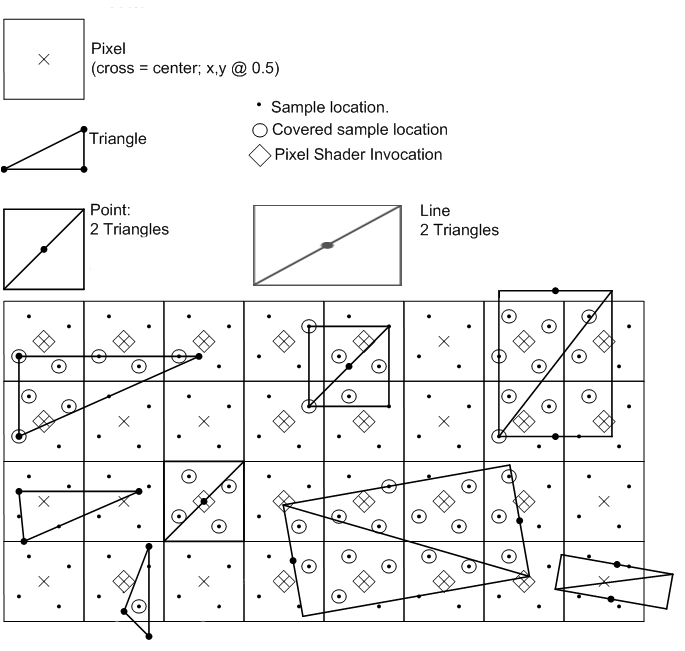
By using the coverage mask to determine which subsamples to be updated, the end result is that a single pixel can end up storing the output from N different triangles that partially cover the sample pixel. This effectively gives us the result we want, which is an oversampled form of triangle visibility. The following image, taken from the Direct3D 10 documentation[1], visually summarizes the rasterization process for the case of 4xMSAA:
MSAA Resolve
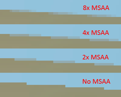
As with supersampling, the oversampled signal must be resampled down to the output resolution before we can display it. With MSAA, this process is referred to as resolving the render target. In its earliest incarnations, the resolve process was carried out in fixed-function hardware on the GPU. The filter commonly used was a 1-pixel-wide box filter, which essentially equates to averaging all subsamples within a given pixel. Such a filter produces results such that fully-covered pixels end up with the same result as non-MSAA rendering, which could be considered either good or bad depending on how you look at it (good because you won’t unintentially reduce details through blurring, bad because a box filter will introduce postaliasing). For pixels with triangle edges, you get a trademark gradient of color values with a number of steps equal to the number of sub-pixel samples. Take a look at the following image to see what this gradient looks like for various MSAA modes:
One notable exception to box filtering was Nvidia’s “Quincunx” AA, which was available as a driver option on their DX8 and DX9-era hardware (which includes the RSX used by the PS3). When enabled, it would use a 2-pixel-wide triangle filter centered on one of the samples in a 2x MSAA pattern. The “quincunx” name comes the fact that the resolve process ends up using 5 subsamples that are arranged in the cross-shaped quincunx pattern. Since the quincunx resolve uses a wider reconstruction filter, aliasing is reduced compared to the standard box filter resolve. However, using a wider filter can also result in unwanted attenuation of higher frequencies. This can lead to a “blurred” look that appears to lack details, which is a complaint sometimes levied against PS3 games that have used the feature. AMD later added a similar feature to their 3 and 4000-series GPU’s called “Wide Tent” that also made use of a triangle filter with width greater than a pixel.
As GPU’s became more programmable and the API’s evolved to match them, we eventually gained the ability to perform the MSAA resolve in a custom shader instead of having to rely on an API function to do that. This is an ability we’re going to explore in the following article.
Compression
As we saw earlier, MSAA doesn’t actually improve on supersampling in terms of rasterization complexity or memory usage. At first glance we might conclude that the only advantage of MSAA is that pixel shader costs are reduced. However this isn’t actually true, since it’s also possible to improve bandwidth usage. Recall that the pixel shader is only executed once per pixel with MSAA. As a result, the same value is often written to all N subsamples of an MSAA render target. GPU hardware is able to exploit this by sending the pixel shader value coupled with another value indicating which subsamples should be written, which acts as a form of lossless compression. With such a compression scheme the bandwidth required to fill an MSAA render target can be significantly less than it would be for the supersampling case.
CSAA and EQAA
Since its introduction, the fundamentals of MSAA have not seen significant changes as graphics hardware has evolved. We already discussed the special resolve modes supported by the drivers for certain Nvidia and ATI/AMD hardware as well as the ability to arbitrarily access subsample data in an MSAA render target, which are two notable exceptions. A third exception has been Nvidia’s Coverage Sampling Antialiasing(CSAA)[2] modes supported by their DX10 and DX11 GPU’s. These modes seek to improve the quality/performance ratio of MSAA by decoupling the coverage of triangles within a pixel from the subsamples storing the value output by the pixel shader. The idea is that while subsamples have high storage cost since they store pixel shader outputs, the coverage can be stored as a compact bitmask. This is exploited by rasterizing at a certain subsample rate and storing coverage at that rate, but then storing the actual subsample values at a lower rate. As an example, the “8x” CSAA mode stored 8 coverage samples and 4 pixel shader output values. When performing the resolve, the coverage data is used to augment the quality of the results. Unfortunately Nvidia does not provide public documentation of this step, and so the specifics will not be discussed here. They also do not provide programmatic access to the coverage data in shaders, thus the data will only be used when performing a standard resolve through D3D or OpenGL functions.
AMD has introduced a very similar feature in their 6900 series GPU’s, which they’ve named EQAA[3]. Like Nvidia, the feature can be enabled through driver options or special MSAA quality modes but it cannot be used in custom resolves performed via shaders.
Working with HDR and Tone Mapping
Before HDR became popular in real-time graphics, we essentially rendered display-ready color values to our MSAA render target with only simple post-processing passes applied after the resolve. This meant that after resolving with a box filter, the resulting gradients along triangle edges would be perceptually smooth between neighboring pixels3. However when HDR, exposure, and tone mapping are thrown into the mix there is no longer anything close to a linear relationship between the color rendered at each pixel and the perceived color displayed on the screen. As a result, you are no longer guaranteed to get the smooth gradient you would get when using a box filter to resolve LDR MSAA samples. This can seriously affect the output of the resolve, since it can end up appearing as if no MSAA is being used at all if there is extreme contrast on a geometry edge.
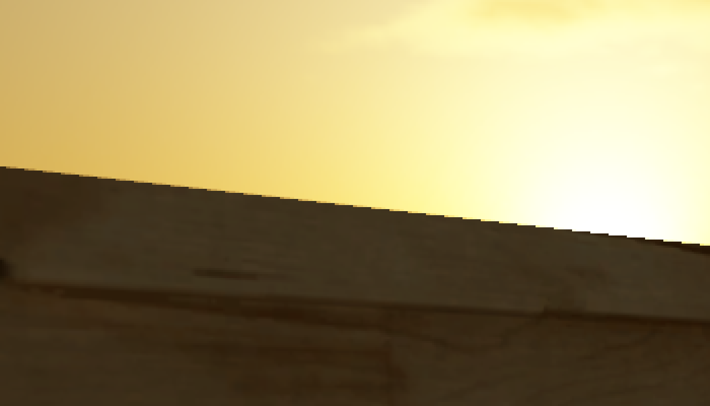
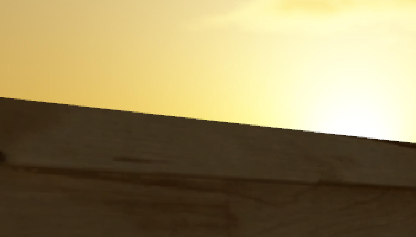
This strange phenomenon was first pointed out (to my knowledge) by Humus (Emil Persson), who created a sample[4] demonstrating it as well as a corresponding ShaderX6 article. In this same sample he also demonstrated an alternative approach to MSAA resolves, where he used a custom resolve to apply tone mapping to each subsample individually before filtering. His results were pretty striking, as you can see from these images (left is a typical resolve, right is resolve after tone mapping):
It’s important to think about what it actually means to apply tone mapping before the resolve. Before tone mapping, we can actually consider ourselves to be working with values representing physical quantities of light within our simulation. Primarily, we’re dealing with the radiance of light reflecting off of a surface towards the eye. During the tone mapping phase, we attempt to convert from a physical quantity of light to a new value representing the color that should be displayed on the screen. What this means is that by changing where the resolve takes places, we’re actually oversampling a different signal! When resolving before tone mapping we’re oversampling the signal representing physical light being reflected towards the camera, and when resolving after tone mapping we’re oversampling the signal representing colors displayed on the screen. Therefore an important consideration we have to make is which signal we actually want to oversample. This directly ties into post-processing, since a modern game will typically have several post-processing effects needing to work with HDR radiance values rather than display colors. Thus we want to perform tone mapping as the last step in our post-processing chain. This presents a potential difficulty with the approach of tone mapping prior to resolve, since it means that all previous post-processing steps must work with a non-resolved MSAA as an input and also produce an MSAA buffer as an output. This can obviously have serious memory and performance implications, depending on how the passes are implemented.
Update 8/26/2017: a much simpler and more practical alternative to performing tone mapping at MSAA resolution is to instead use the following process:
- During MSAA resolve of an HDR render target, apply tone mapping and exposure to each sub-sample
- Apply a reconstruction filter to each sub-sample to compute the resolved, tone mapped value
- Apply the inverse of tone mapping and exposure (or an approximation) to go back to linear HDR space
Doing it this way lets you apply the resolve before post-processing, while still giving you much higher-quality results than a standard resolve. I’m not sure who originally came up with this idea, but I recall seeing it mentioned on the Beyond3D forums many years ago. Either way it was popularized by Brian Karis through a blog post. You can see it in action in my updated MSAA/TAA sample on GitHub, as well as in my presentation from SIGGRAPH 2015.
MLAA and Other Post-Process AA Techniques
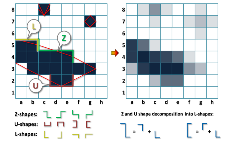
Morphological Anti-Aliasing is an anti-aliasing technique originally developed by Intel[5] that initiated a wave of performance-oriented AA solutions commonly referred to as post-process anti-aliasing. This name is due to the fact that they do not fundamentally alter the rendering/rasterization pipeline like MSAA does. Instead, they work with only a non-MSAA render target to produce their results. In this way these techniques are rather interesting, in that they do not actually rely on increasing the sampling rate in order to reduce aliasing. Instead, they use what could be considered an advanced reconstruction filter in order to approximate the results that you would get from oversampling. In the case of MLAA in particular, this reconstruction filter uses pattern-matching in an attempt to detect the edges of triangles. The pattern-matching relies on the fact that for a fixed sample pattern, common patterns of pixels will be produced by the rasterizer for a triangle edge. By examining the color of the local neighborhood of pixels, the algorithm is able to estimate where a triangle edge is located and also the orientation of the line making up that particular edge. The edge and color information is then enough to estimate an analytical description of that particular edge, which can be used to calculate the exact fraction of the pixel that will be covered by the triangle. This is very powerful if the edge was calculated correctly, since it eliminates the need for multiple sub-pixel coverage samples. In fact if the coverage amount is used to blend the triangle color with the color behind that triangle, the results will match the output of standard MSAA rendering with infinite subsamples! The following image shows some of the patterns used for edge detection, and the result after blending:
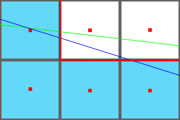
The major problems with MLAA and similar techniques occur when the algorithm does not accurately estimate the triangle edges. Looking at only a single frame, the resulting artifacts would be difficult or impossible to discern. However in a video stream the problems become apparent due to sub-pixel rotations of triangles that occur as the triangle or the camera move in world space. Take a look at the following image:
In this image, the blue line represents a triangle edge during one frame and the green line represents the same triangle edge in the following frame. The orientation of the edge relative to the pixels has changed, however in both cases only the leftmost pixel is marked as being “covered” by the rasterizer. Consequently the same pixel pattern (marked by the blue squares in the image) is produced by the rasterizer for both frames, and the MLAA algorithm detects the same edge pattern (denoted by the thick red line in the image). As the edge continues rotating, eventually it will cover the top-middle pixel’s sample point and that that pixel will “turn on”. In the resulting video stream that pixel will appear to “pop on”, rather than smoothly transitioning from a non-covered state to a covered state. This is a trademark temporal artifact of geometric aliasing, and MLAA is incapable of reducing it. The artifact can be even more objectionable for thin or otherwise small geometry, where entire portions of the triangle will appear and disappear from frame to frame causing a “flickering” effect. MSAA and supersampling are able to reduce such artifacts due to the increased sampling rate used by the rasterizer, which results in several “intermediate” steps in the case of sub-pixel movement rather than pixels “popping” on and off. The following animated GIFs demonstrate this effect on a single rotating triangle4
Another potential issue with MLAA and similar algorithms is that they may fail to detect edges or detect “false” edges if only color information is used. In such cases the accuracy of the edge detection can be augmented by using a depth buffer and/or a normal buffer. Another potential issue is that the algorithm uses the color adjacent to a triangle as a proxy for the color behind the triangle, which could actually be different. However this tends to be non-objectionable in practice.
References
[1] http://msdn.microsoft.com/en-us/library/windows/desktop/cc627092%28v=vs.85%29.aspx
[2] http://www.nvidia.com/object/coverage-sampled-aa.html
[3] http://developer.amd.com/Resources/archive/ArchivedTools/gpu/radeon/assets/EQAA Modes for AMD HD 690 Series Cards.pdf
[4] http://www.humus.name/index.php?page=3D&ID=77
[5] MLAA: Efficiently Moving Antialiasing from the GPU to the CPU
Next article in the series: Experimenting with Reconstruction Filters for MSAA Resolve
Comments:
Noticias 11-11-2012 - La Web de Programación -
[…] Excelente artículo explicando que es el MSAA (Multi Sampling Anti Aliasing): Técnico y detallado. […]
#### [A Closer Look At Mantle and EQAA In Civilization](http://forums.hexus.net/graphics-cards/332789-closer-look-mantle-eqaa-civilization.html#post3400117 "") -
[…] every pixel to be tested for color and coverage in two, four or eight locations. Learn More: MSAA Overview Like MSAA, AMD’s Enhanced Quality Anti-Aliasing (EQAA) also comes in 2x, 4x and 8x sampling […]
#### [Brian Breczinski (@BrianBreczinski)](http://twitter.com/BrianBreczinski "BrianBreczinski@twitter.example.com") -
“This means that the pixel shader performance does not increase substantially when MSAA is enabled, which is the primary benefit of MSAA over supersampling.” I think you mean “decrease”
#### [MJP](http://mynameismjp.wordpress.com/ "mpettineo@gmail.com") -
Yeah I actually meant to write “pixel shader cost”. Thanks for pointing that out!
#### [Anonymous Coward]( "") -
Excellent article. This means that the pixel shader performance does not *increase* substantially when MSAA is enabled –> This means that the pixel shader performance does not *decrease* substantially when MSAA is enabled
#### [AMD reigns supreme in Sid Meier’s Civilization: Beyond Earth | ArdzTV](http://ardz.tv/amd-reigns-supreme-in-sid-meiers-civilization-beyond-earth/ "") -
[…] LEARN MORE: A Quick Overview of MSAA […]
#### [Niels Fröhling (@Ethatron)](http://twitter.com/Ethatron "niels@paradice-insight.us") -
“Working with HDR and Tone Mapping”: The fundamental underlying problem is that the color-space is non-linear. You’ll also get a wrong resolve with simple LDR sRGB because the filtering is done in the wrong domain (linear filtering in a non-linear domain). It may not be very visible in LDR sRGB, and maybe the hardware has sRGB-filtering as a special case in some fixed function block, given the rendertarget is marked to be sRGB, and textures translate from sRGB to RGB while being fetched. You can always make it “right” by using a linear color-space (linear means the euclidian distance between two values in any part of the range is identical respective the change in energetic magnitude). In the case of sRGB it’s rather easy, as the “tonemapper” is a simple gamma-function which is easily invertible (you have to store shader-output in linear RGB), but if you use a custom tonemapping-curve you may end up with a situation of uninvertability, and you don’t know how to store the values in the rendertarget to be linearly filterable. What Humus is basically doing is translating the output of his shaders into a linearly filterable form, it’s not really an exclusive artifact of HDR, and that linear color-space can still be HDR, it’s not necessary for the values to collapse into [0,255] space (like “normal” tonemapper would do), the only requirement is that the color-space is linear. That’s my understanding of it, maybe I just oversee some aspect.
#### [drbaltazar]( "Michelmrnet@hotmail.com") -
As for linear ? Best bet would be to all use scrgb but given how big it is ,not sure it is a great idea !
#### [drbaltazar]( "Michelmrnet@hotmail.com") -
Too many assumption in this thread !you assume everybody have a 100% sRGB monitor that can do 0 to 255 ,average is 3 to 252 so imagine what happen to all the data .imagine how screwed up the gamma curve will subtle ?ROFL let me recap ,user cannot adjust the min 0 black point to the proper value (average being 3 that would be in fact the real 0 ,this part is pretty much fixed in color.org profile so you say now gamma is accurate white point is accurate ? Right ? Nope because then user meet another problem ms doesn’t supply a setting for max white value on average poor man screen max is 252 all color profile expect 255 .guess what happen ? Yep most white get crushed (just like that black get crushed )worst the gamma isn’t gonna be at proper value because it expect 0 to 255 when in fact you are at 3 to 252 .even color.org fixed version is wrong because it assume 3 to 255 .so you still get gamma issue .and white point in this ?ya you get the idea .so add all the fix in this and its no wonder image look bad at time !simplest fix ? Add a way to adjust minimum for 0 to 3 and add a way to set max from 252 to 255 ms and all would yell :but just buy a proper monitor that do 0 to 255 100% sRGB .I’m sure nobody will listen to this advice .lastly everybody assume copy protection in HDMI, dvi, dp is really letting game signal do their thing .I aint sure it does .I begin to suspect part of what game Dev use is copy protected and if license wasn’t paid ? Ya you get the idea .its all fine and good to ignore a lot of stuff but game Dev artist are so good now almost nobody need msaa or all the other post process .and lastly tearing and jagged is created way before the memory even get that data so what does it ? Its the various buffer timing of memory cache etc that cause it .and only is maker be it ms or Linux can fix this .seeing new android stuff I think Google has almost fixed it .(ya I was surprised)me if I was Dev I would disable msaa and all and find the issue in os and then notify ms so they can adjust those value to proper number since these setting have been avail for almost ever
#### [Priyadarshi Sharma](https://www.facebook.com/priyadarshi1 "priyadarshi.sh@gmail.com") -
Great article! I really like the way you write. It’s similar (or even better) to the style used in books like Physically based Rendering and Real-time rendering. You should write one!
#### [Ben Supnik’s … A Flicker of Hope for Flicker | Aerosoft Sim News](http://asn.aerosoft.com/?p=15514 "") -
[…] the prospect of explaining them was daunting. Fortunately Matt Pettineo did an awesome job with this post. Go read it; I’ll wait […]
#### [A Flicker of Hope for Flicker | X-Plane Developer](http://developer.x-plane.com/2012/11/a-flicker-of-hope-for-flicker/ "") -
[…] the prospect of explaining them was daunting. Fortunately Matt Pettineo did an awesome job with this post. Go read it; I’ll wait […]
#### [AMD reigns supreme in Sid Meier’s Civilization: Beyond Earth | Daily Cliche](http://www.dailycliche.com/amd-reigns-supreme-in-sid-meiers-civilization-beyond-earth/ "") -
[…] LEARN MORE: A Quick Overview of MSAA […]
#### [VR distortion correction using vertex displacement - GeekTechTalk](http://www.geektechtalk.com/vr-distortion-correction-using-vertex-displacement/ "") -
[…] up the MSAA – if you are unfamiliar with what MSAA does other than remove jaggies – I suggest a quick read here – or otherwise just accept that turning on 4x MSAA is a little bit like rendering on a screen […]
#### [Ogre Progress Report: December 2017 | OGRE - Open Source 3D Graphics Engine](https://www.ogre3d.org/2018/01/01/ogre-progress-report-december-2017 "") -
[…] may have heard that combining HDR and MSAA can still results in nasty aliasing. Sometimes even make it worse. This can happen if you’re looking at a very dark object with a […]
#### [OpenGLのCompute shaderでアンチエイリアシングを実装する | tatsyblog](http://tatsyblog.sakura.ne.jp/wordpress/applications/graphics/1651/ "") -
[…] Quick Overview of MSAA – https://mynameismjp.wordpress.com/2012/10/24/msaa-overview/ […]
#### [MJP](http://mynameismjp.wordpress.com/ "mpettineo@gmail.com") -
Thank you Simon! The error is now fixed. :)
#### [Simon](http://simonschreibt.de "simon@simonschreibt.de") -
Wonderful article - very well written and understandable. I’ve found a tiny error and I just tell it because I like it when people point me to things like this on my own blog. :) I guess here’s an “is” too much: “This is exploited is by rasterizing” Thanks again for your time you invested in this. *thumbs up*
#### [Anti-aliasing technics comparison - SAPPHIRE Nation - Community blog by SAPPHIRE Technology](http://sapphirenation.net/anti-aliasing-technics-comparison/ "") -
[…] Performance-wise, MSAA is a major improvement over SSAA. The boost was achieved by sampling two or more adjacent pixels together, instead of rendering the entire scene at a very high resolution. Thanks to that, further optimizations can be performed to share samples between different pixels. For example, if there is a group of pixels of similar colors, not every single one needs to be analyzed entirely—and that’s what boosts performance. SSAAx4 means a single pixel requires four samples, but with MSAAx4 some samples can be split between adjacent pixels, thus freeing up computational power. This is why MSAA is so much faster than SSAA. The main drawback of MSAA is the lower image quality it produces. It simply can’t deal with transparencies, a fact that is clearly visible in most modern games. If you want to learn something more about MSAA, take a look here. […]
#### [Anti-Aliasing Research - Programming Money](http://www.programmingmoney.com/anti-aliasing-research/ "") -
[…] In-depth explanation of Anti-Aliasing: https://mynameismjp.wordpress.com/2012/10/24/msaa-overview/ […]
#### [Beware of SV_Coverage – Yosoygames](http://www.yosoygames.com.ar/wp/2017/02/beware-of-sv_coverage/ "") -
[…] Neither GL spec, docs, MSDN docs and other readings warned me about these gotchas. MJP’s blogposts were very useful, but that’s it. And they weren’t very specific to […]
-
The rasterization process on a modern GPU can actually be quite a bit more complicated than this, but those details aren’t particularly relevant to the scope of this article. ↩︎
-
This mask is directly available to ps_5_0 pixel shaders in DX11 via the SV_Coverage system value. ↩︎
-
The gamma-space rendering commonly used in the days before HDR would actually produce gradients that weren’t completely smooth, although later GPU’s supported performing the resolve in linear space. Either way the results were pretty close to being perceptually smooth, at least compared to the results that can occur with HDR rendering. ↩︎
-
These animations were captured from the sample application that I’m going to discuss in the next article. So if you’d like to see live results without compression, you can download the sample app from that article. ↩︎
