Radiosity, DX11 Style
Radiosity isn’t exactly new. According to Wikipedia it’s been used for rendering since the early 80’s, and this page looks like it may have been the first web page on the Internet. The basic premise is dead simple: for each point where you want to bake lighting (typically either a texel in a lightmap, or a vertex in a mesh), render the rest of the scene and any exterior light sources (skydome, area lights, sun, whatever) in all directions within a hemisphere surrounding the surface normal at that point. As described in the article I linked, this is typically done by rendering 5 faces of a hemicube so as to play nice with a traditional perspective projection. It’s possible to use a parabolic projection for this (as in dual-paraboloid shadow mapping), but there are problems you can run into which are outlined here. Once you’ve fully rendered your hemisphere, you then integrate your computed radiance about the hemisphere with a cosine kernel to compute irradiance, which you can use to determine the diffuse reflectance for that point. You can then store this diffuse lighting value in your vertex or lightmap texel, and you’re ready to render your geometry fully lit by direct lighting. Typically you repeat the process many times, rendering the geometry scene geometry as lit by the results of your previous iteration. This effectively allows you to compute lighting for each successive bounce off the scene geometry, adding an indirect lighting term. With enough iterations, you eventually begin to converge on a full global illumination solution for diffuse lighting. The nice part about the technique is that it’s pretty simple to implement…if you can rasterize a mesh you’re already most of the way there, and you can even co-opt an existing real-time rendering engine to do it. Taking the latter approach has the added benefit that any material or lighting feature you add to your engine benefits your radiosity baker by default…so for instance if you have some complex pixel shader that blends multiple maps to determine the final material albedo, you don’t need to implement an equivalent solution in a ray tracer or photon mapper. You can even take advantage of your lighting and shadowing pipeline, if you do it right. The major downside is that it’s usually pretty slow, even if you implement it all on the GPU. This is because you typically have to serialize rendering of the scene for each vertex or lightmap texel, rather than baking many vertices/texels in parallel (which is possible with ray tracing implementations, particularly if you do it on the GPU using Cuda/Optix). Recently when I was trying to get myself familar with GI techniques, I decided to implement my own radiosity baker (with a lot of help from my coworker Dave). However to make it cool and hip for the DX11 age, I deviated from the “standard” radiosity process in 3 ways:
-
Rather than producing a single diffuse color per sample point, I baked down to a set of 1st-order H-basis coefficients representing irradiance about the hemisphere. This lets you use normal mapping with your baked values, which adds higher fidelity to your precomputed lighting. This is similar to what Valve, Bungie, and Epic do for their lightmaps, except I’m using a different basis. If you’re not familiar with H-basis, they’re similar to spherical harmonics except that they’re only defined on the upper hemisphere. This allows you to get better quality with less coefficients, for situations where you only need to store information about a hemisphere rather than a full sphere.
-
Instead of baking direct lighting for all light sources, I bake direct + indirect lighting for a skydome and indirect lighting only for the sun. This is similar to what Naughty Dog does in Uncharted. The advantage is that you can add in the direct sun lighting at runtime using a directional light, and you get nice high-frequency visibility from your shadow maps. This lets you avoid having to use an area light or environment map for representing your sun, which can be difficult to tune if you’re used to traditional analytical directional light sources. Plus you can light your dynamic geometry the same way and have the lighting match, and also have their dynamic shadows only remove the direct lighting term. Another additional advantage is that your baked lighting term generally only contains low-frequency information, since it doesn’t need to represent high frequency shadow visibility from the direct term. So if your scene is decently tessellated you can get away with computing it per-vertex, which is what I did.
-
I used compute shaders for integrating the radiosity hemicube down to H-basis coefficients. This not only made the integration really really fast, but it let me keep everything on the GPU and avoid messing with CPU-GPU memory transfers.
Setup
To prepare for baking, the scene and all of its individual meshes are loaded and processed. As part of the processing, I calculate a per-vertex tangent frame using a modified version of this approach. The tangents are needed for normal mapping, but they’re also used as a frame of reference for baking each vertex. This is because I store H-basis irradiance in tangent space. Tangent space provides a natural frame of reference for the hemisphere about the normal, and is also consistent across the vertices of a triangle. This lets me interpolate the coefficients across a triangle, which wouldn’t be possible if each vertex used a different frame of reference during integration. It also allows for a simple irradiance lookup with the tangent space normal sampled from a normal map, or (0, 0, 1) if normal mapping isn’t used.
Baking
The baking loop looks something like this:
for each Iteration
    for each Mesh
        Extract vertex data
        for each Vertex
            for each Hemicube Face
                if 1st iteration
                    Render the scene, depth only
                    Render the skydome
                else if 2nd iteration
                    Render the scene with baked lighting + shadowed diffuse from the sun
                else
                    Render the scene with baked lighting
            Integrate
     Sum the result of current iteration with result of previous iteration
Basically we do N + 1 iterations, where N is the number of indirect bounces we want to factor in. For the first iteration we add in all direct light sources (the skydome), for the second we add in the bounce lighting from the first pass plus the indirect-only lighting (the sun), and in all subsequent passes we only render the scene geometry with baked lighting.
Vertex Baking
For each vertex, we need to determine the radiance emitted from each surface visible around the hemisphere. This hemisphere of radiance values is known as the field-radiance function. Determining the radiance value for any surface is simple: we just render the corresponding mesh and evaluate the BRDF in the pixel shader, which in our case means sampling the albedo texture and using it to modulate the diffuse lighting. Since we’re going do it using rasterization, we’ll render to a hemicube for the reasons mentioned previously. To represent my hemicube, I used 5 R16G16B16A16_FLOAT render target textures storing HDR color values. To keep things simple I made them all equal-sized, and rendered each face as if it were a full cube map rather than a hemicube. However I used the scissor test to scissor out the half of the cube face that would not be needed, for all faces other than the first. Initially I used 256x256 textures for the render targets, but eventually lowered it to 64x64. Increasing the resolution does increase the quality slightly, but gains become diminishing very quickly past 64x64. This is because the irradiance integration filters out the high-frequency components, so any small details missed due to the small render target size have very little effect on the end result. For the first pass, the scene is rendered with color writes disabled. This is because the mesh surfaces do not yet have incident lighting, and thus do not emit any radiance. Conceptually you can imagine this as though all light sources just began emitting light, and the light has yet to reach the mesh surfaces. So essentially we just render the mesh geometry to the depth buffer, in order “block out” the sky and determine the overall visibility for that vertex. Once we’ve done this we render the skydome with a depth value of 1.0, so that any rendered geometry occludes it. Thus we “fill in” the rest of the hemicube texels with radiance values emitted by the skydome. For the skydome I used the CIE Clear Sky model, which is simple and easy to implement in a pixel shader. The final result in the hemicube textures looks like this: 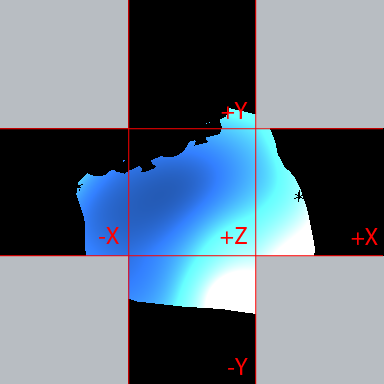 For the second pass, we use the results of the first pass as the incident lighting light for each surface pixel. This effectively causes the skydome lighting to “bounce” off the surface, adding indirect lighting. We also evaluate the diffuse contribution from the sun for each pixel, so that we get an indirect contribution from the sun as well. This contribution is calculated using a simple N (dot) L with the interpolated vertex normal, and the sun direction. A shadow visibility term is also added using a shadow map, which is rendered as a low-resolution cascaded shadow map. Then the sum of the baked lighting and and the sun light are modulated with the diffuse albedo, which is sampled from a texture. So the final exit radiance value for a pixel is computed like this:
radiance = (bakedLighting + sunLight * sunVisibility) * diffuseAlbedo
After the scene is rendered, the skydome is omitted since it’s contribution was already handled in the first pass. Thus the final hemicube looks like this: 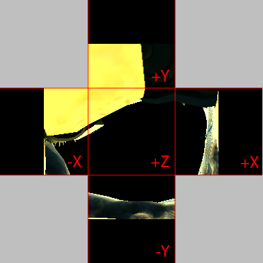 For all subsequent passes, only the baked vertex irradiance is used for computing the exit radiance of each pixel. This is because the contribution from both of our light sources have already been added in previous passes, and we only need to further compute indirect lighting terms.
Integration
Once we’ve rendered the scene to all 5 sides of the hemicube, we have a full field-radiance function for the hemisphere stored in a texture map. At this point we could now compute a full irradiance distribution function for the hemisphere, which would provide us with an irradiance value for any possible surface normal. Such a function would be computed by convolving our field radiance with a cosine kernel, which is done by evaluating the following integral:
$$ I(p,N_{p})=\int_{\Omega}L(p,\omega_{i})(N_{p}\circ\omega_{i})d\omega_{i} $$
Unfortunately, a full irradiance distribution function in a texture map isn’t all that useful since it’s too much data to store per-vertex. So instead we’ll represent the irradiance map using 2nd-order spherical harmonics, using the method outlined in the paper “An Efficient Representation for Irradiance Environment Maps”. The basic procedure is to first convert the radiance map to a spherical harmonic representation by integrating against the spherical harmonic basis functions, and then convolve the result with a cosine kernel to compute irradiance. The following integral is used for projecting onto SH:
$$ L_{lm}=\int_{\theta=0}^{\pi}\int_{\phi=0}^{\pi}L(\theta,\phi)Y_{lm}(\theta,\phi)sin{\theta}d{\theta}d{\phi} $$
For radiance stored in a texture map, we can implement this integration by using the method described in Peter-Pike Sloan’s Stupid Spherical Harmonics Tricks. For our purposes we’ll modify the algorithm by first converting each texel’s SH radiance to irradiance by convolving with a cosine kernel, and then converting the SH coefficients to 1st-order H-basis representation. This allows us to sum 12 values per texel, rather than the 27 required for 2nd-order SH. The algorithm looks something like this:
for each Hemicube Face
    for each Texel
        Sample radiance
        Calculate direction vector for the texel
        Project the direction onto SH and convolve with cosine kernel
        Multiply SH coefficients by sampled radiance
        Convert from SH to H-basis
        Weight the coefficients by the differential solid angle for the texel
        Add the coefficients to a running sum
What this essentially boils down to is bunch of per-texel math, followed by sum of all results. Sounds like a job for compute shaders! The first part is simple, since the per-texel math operations are completely independent of one another. The second part is a bit tougher, since it requires a parallel reduction to be efficient. Essentially we need to efficiently share results between different threads in order to avoid heavy bandwidth usage, while properly exploiting the GPU’s massively parallel architecture by sharing the workload across multiple minimally divergent threads and thread groups. Basically it’s pretty simple to implement naively, and tricky to do it with good performance. Fortunately Nvidia has a bunch of data-parallel algorithms that are part of their cuda SDK, and one of them happens to be a parallel reduction. I won’t go into the details, but their whitepaper outlines the basic process as well as a series of improvements that can be made to the naive algorithm in order to improve performance. These improvements are a mix of algorithmic and hardware-specific optimizations, and pretty much all of them are easily applicable to compute shaders.
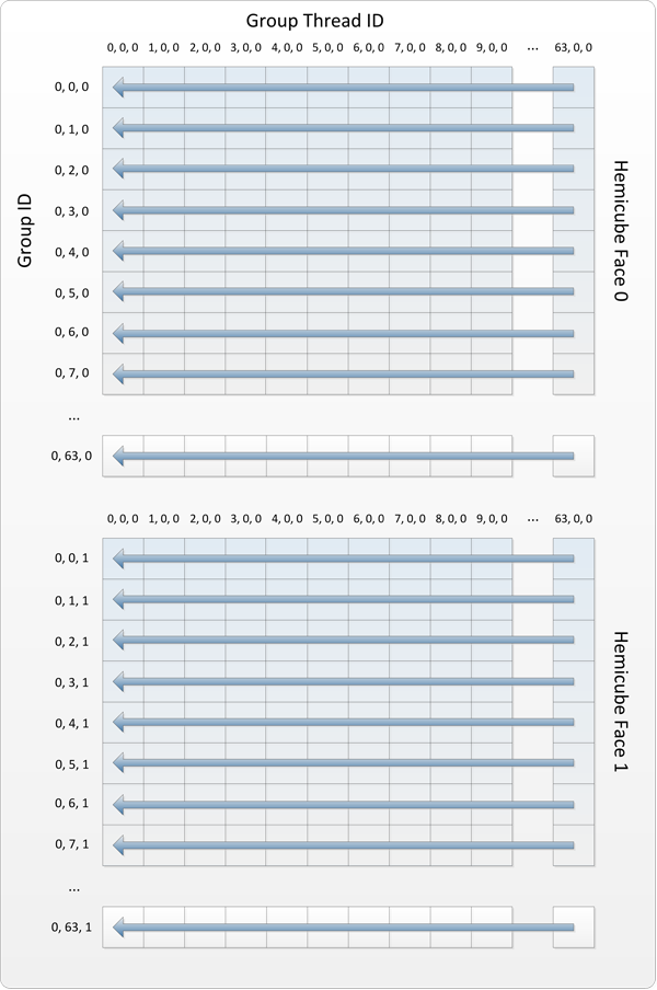
My implementation ended up being 2 passes: the first performing the conversion to H-basis irradiance and reducing each row of each face texture to a single set of RGB coefficients, and the second reducing to only 1 set of RGB coefficients. In the first pass, the threads are dispatched in 1x64x5 thread groups, with each group containing 64x1x1 threads. The following diagram shows how the threads are distributed relative to the hemicube textures for the first 2 faces:
The projection onto SH and cosine kernel convolution can be implemented pretty easily in HLSL, using values taken from the irradiance environment mapping paper. My HLSL code looks like this:
void ProjectOntoSH(in float3 n, in float3 color, out float3 sh[9])
{
    // Cosine kernel
    const float A0 = 3.141593f;
    const float A1 = 2.095395f;
    const float A2 = 0.785398f;

    // Band 0
    sh[0] = 0.282095f * A0 * color;

    // Band 1
    sh[1] = 0.488603f * n.y * A1 * color;
    sh[2] = 0.488603f * n.z * A1 * color;
    sh[3] = 0.488603f * n.x * A1 * color;

    // Band 2
    sh[4] = 1.092548f * n.x * n.y * A2 * color;
    sh[5] = 1.092548f * n.y * n.z * A2 * color;
    sh[6] = 0.315392f * (3.0f * n.z * n.z - 1.0f) * A2 * color;
    sh[7] = 1.092548f * n.x * n.z * A2 * color;
    sh[8] = 0.546274f * (n.x * n.x - n.y * n.y) * A2 * color;
}
Converting that to H-basis is also simple, and is expressed as a matrix multiplication. The values for the transformation matrix are given in the source paper. This is the shader code that I used:
void ConvertToHBasis(in float3 sh[9], out float3 hBasis[4])
{
    const float rt2 = sqrt(2.0f);
    const float rt32 = sqrt(3.0f / 2.0f);
    const float rt52 = sqrt(5.0f / 2.0f);
    const float rt152 = sqrt(15.0f / 2.0f);
    const float convMatrix[4][9] =
    {
        { 1.0f / rt2, 0, 0.5f * rt32, 0, 0, 0, 0, 0, 0 },
        { 0, 1.0f / rt2, 0, 0, 0, (3.0f / 8.0f) * rt52, 0, 0, 0 },
        { 0, 0, 1.0f / (2.0f * rt2), 0, 0, 0, 0.25f * rt152, 0, 0 },
        { 0, 0, 0, 1.0f / rt2, 0, 0, 0, (3.0f / 8.0f) * rt52, 0 }
    };

    [unroll(4)]
    for(uint row = 0; row < 4; ++row)
    {
        hBasis[row] = 0.0f;

        [unroll(9)]
        for(uint col = 0; col < 9; ++col)
            hBasis[row] += convMatrix[row][col] * sh[col];
    }
}
After the first pass, we’re left with a single buffer containing 64x5x3 float4 values, where each consecutive set of 3 float4 values represents the sum of all RGB H-basis coefficients for that row. To reduce to a single set of coefficients, we dispatch a reduction pass containing 1x3x1 groups of 64x1x5 threads. With this setup each group sums all 64 of the R, G, or B coefficients for a particular hemicube face and stores the result in shared memory. Once this has completed, the first thread of each group sums the 5 values for each hemicube to produe a single set of H-basis coefficients. This last step is somewhat sub-optimal since only a single thread performs the work, however for summing only 5 values I didn’t think it was worth it to try anything fancy or split the reduction into another pass. The following diagram shows the thread layout:
The final result of this process is 3 sets of 4 H-basis coefficients (1 for each RGB channel) representing the irradiance across the hemisphere around the vertex normal, oriented in tangent space. After vertices are baked in this manner, I sum the vertex coefficients for each mesh with the results from the previous iteration in order to sum the bounces (which I do with a really simple compute shader). After the desired number of iterations, the coefficients are ready to be used at runtime and combined with direct sun lighting. Evaluating the H-basis coefficients to compute irradiance for a normal is pretty simple. I use the following code in my pixel shader, which takes a tangent space normal and the interpolated coefficients from the vertices:
float3 GetHBasisIrradiance(in float3 n, in float3 H0, in float3 H1, in float3 H2, in float3 H3)
{
    float3 color = 0.0f;

    // Band 0
    color += H0 * (1.0f / sqrt(2.0f * 3.14159f));

    // Band 1
    color += H1 * -sqrt(1.5f / 3.14159f) * n.y;
    color += H2 * sqrt(1.5f / 3.14159f) * (2 * n.z - 1.0f);
    color += H3 * -sqrt(1.5f / 3.14159f) * n.x;

    return color;
}
Performance
To enable profiling with quick iteration, I made a very simple test scene containing a single mesh and 12,400 vertices. My initial implementation was pretty slow, baking only 545 vertices per second for the 1st pass, 292 vps for the 2nd pass, and close to 545 for all subsequent passes. For the first pass, I determined that the integration step was slowing things down considerably. Initially I had implemented integration using pixel shaders, which converted to H-basis and then reduced each hemicube face by a 1/4 each pass. This resulted in lots of unnecessary render target reads and writes, degrading performance. Moving to my current compute shader implementation brought the first pass to 1600 vps, and the second pass to 325 vps. When I analyzed the second pass, GPU PerfStudio revealed that I was spending a significant amount of time in the geometry shader during the main rendering and shadow map rendering phases. I had used a geometry shader so that I could create the 5 hemicube faces as a texture array (or 4 shadow map cascades for the shadow map), and use SV_RenderTargetArrayIndex to specify the output array slice without having to switch render targets multiple times. I had known that this sort of geometry shader amplification performed poorly on Dx10 hardware and had been hoping that it wouldn’t be so bad on my 5830, but unfortunately this was not the case. Ditching the geometry shader and setting the render target slices one by one brought me up to 1760 vps for the first pass and 480 vps for the second pass. Further performance was gained by switching the cascaded shadow map implementation to use an old-school texture atlas rather than a texture array, which brought me to 625 vps for the second pass. This was disappointing, since texture arrays are a totally natural and convenient way to implement cascaded shadow maps. Texture atlases are so DX9. Even after that the shadow map rendering was still really slowing down the 2nd pass, so I cut it down to 2 cascades (from 4) and reduced the resolution from 2048x2048 per cascade to 512x512. This got me to 850 vps for the test scene, about 600 vps for the broken tank scene from the SDK, and about 180 vps for the powerplant scene from the SDK. In its current state, the GPU is currently spending a portion of each vertex bake idling due to processing so many commands and having multiple render target switches. It could definitely benefit from some reduction in overall amount of API commands and state changes, and batching during the shadow map rendering. It would also probably benefit from using an approach similar to Ignacio’s, where the shadow map is only rendered once for a group of vertices.
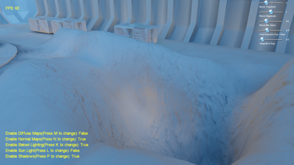
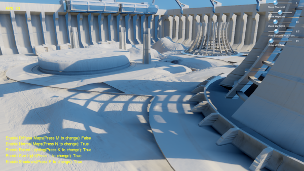
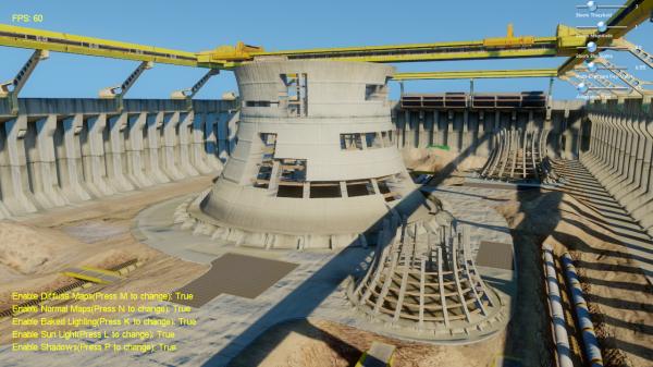
Now for some pictures! These were all taken with only a single bounce, because I’m impatient.
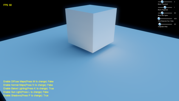
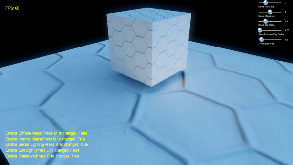
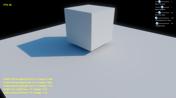
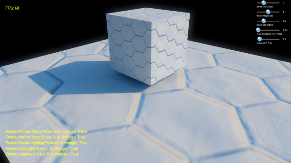
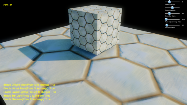
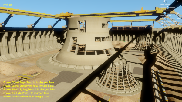
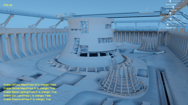
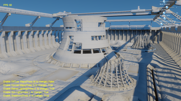
Test scene: baked lighting only, baked lighting with normal maps, baked lighting + direct sunlight, baked light + direct with normal maps, final
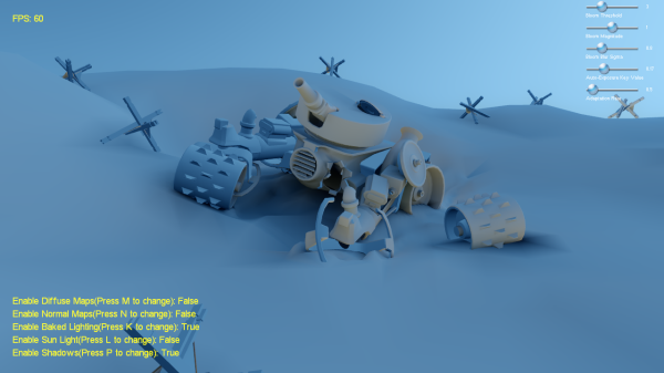
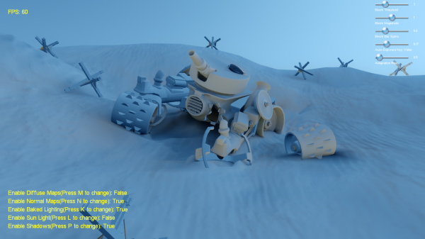
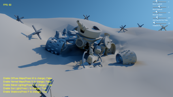
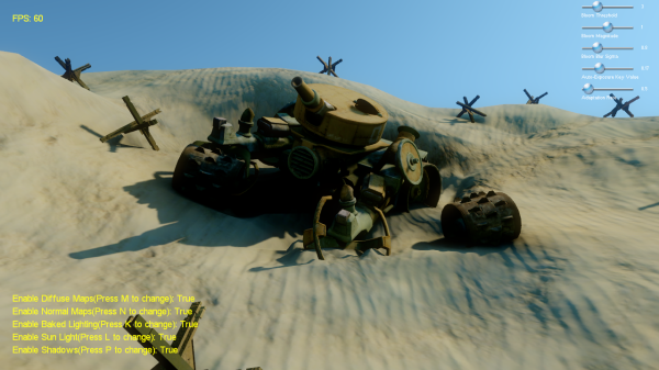
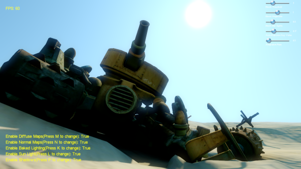
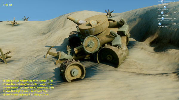
Tank scene: baked only, baked with normal mapping, baked + direct, final, alternate final, another alternate final
Powerplant scene: direct only, baked only, baked + direct, baked w/o normal mapping, baked w/ normal mapping, alternate baked + direct, final
Source code and binaries are available here:
http://mynameismjp.files.wordpress.com/2014/04/radiositydx11.zip
Updated (3/27/2011): Changed the shadow filtering shader code so that it doesn’t cause crashes on Nvidia hardware
Comments:
At this point I’m starting to think you are an ATI fan boy >.<
#### [Ignacio](http://castano.ludicon.com/blog/ "castano@gmail.com") -
Good work! I wish we could port our baker to D3D11. I think that an interesting approach would be to combine the use of texture atlases with geometry shaders by using SV_ViewportArrayIndex. For this to be really effective you really need to use a view independent shadowing method and render multiple hemicubes in the same render target.
#### [mpettineo](http://mynameismjp.wordpress.com/ "mpettineo@gmail.com") -
Yeah…you’re never going to get decent AO with a vertex bake unless you carefully stitch your geometry in the right places, and that’s just not really practical. You could definitely do a better job with light maps, since your texel density is decoupled from the geometry and you could redistribute it as needed. Or you could just use baked lighting for the large-scale GI effects, and rely on SSAO and/or AO maps to provide the small-scale bits.
#### [rake]( "") -
Thanks for the great post! However, the demo crashes on my NVIDIA GTX480 directly after the baking. I get an access violation at RSSetViewports in the nvwgf2um.dll. It looks like the latest NVIDIA drivers screws something up.
#### [Marco]( "marco-we@freenet.de") -
Fantastic article, loved it! Great results!
#### [mpettineo](http://mynameismjp.wordpress.com/ "mpettineo@gmail.com") -
@rake - Sorry to hear that! My coworker had the same problem on his work PC running a GTX465. Unfortunately I don’t have access to a similar GPU at home and my work PC only has a DX10 GPU, so I’ll have to try to get my coworker to debug it for me. @Marco - Thanks! @Ignacio - I’ll have to try that and see what sort of performance I get. I had tried rendering the geometry 5 times and each time specifying a different value for SV_RenderTargetArray index, and even then I was still spending a significant amount of time in the geometry shader (the time seemed to be proportional to the amount of per-vertex data being emitted).
#### [Some interesting news… | eteractions](http://eteractions.wordpress.com/2011/02/01/some-interesting-news/ "") -
[…] And also this one: http://mynameismjp.wordpress.com/2011/01/31/radiosity-dx11-style/ […]
#### [Tweets that mention Radiosity, DX11 Style « The Danger Zone -- Topsy.com](http://topsy.com/mynameismjp.wordpress.com/2011/01/31/radiosity-dx11-style/?utm_source=pingback&utm_campaign=L2 "") -
[…] This post was mentioned on Twitter by Martin Ecker, indickczar. indickczar said: Radiosity, DX11 Style « The Danger Zone http://bit.ly/eQPrTQ あとで、じっくり読む。 […]
#### [Daniel](http://talden.com "dwrightnow@gmail.com") -
Very cool post. I think your quality is heavily limited by not having enough resolution (or regular enough data points) to reproduce good AO in the indirect areas though.
#### []( "") -
Can this be adjusted to calculate PRT?
#### [MJP](http://mynameismjp.wordpress.com/ "mpettineo@gmail.com") -
Yeah, absolutely. In the first pass you would just need to project the sky visibility onto SH, then in subsequent passes you would add in the bounces modulated by the albedo color.
#### [MJP](http://mynameismjp.wordpress.com/ "mpettineo@gmail.com") -
The zip file is now hosted directly on this site, which you can find at the updated link at the bottom of the post. Let me know if you still have problems.
#### [this programmer]( "andresiraola@gmail.com") -
would you please reupload the files? I would like to take a look at it but it seems like they are not online anymore or office live is down. thanks!
#### [First Post – All About Radiosity « wirezapp](http://wirezapp.wordpress.com/2011/10/28/first-post-all-about-radiosity/ "") -
[…] http://mynameismjp.wordpress.com/2011/01/31/radiosity-dx11-style/ […]
#### [MJP](http://mynameismjp.wordpress.com/ "mpettineo@gmail.com") -
No, I didn’t do anything special to avoid interpolation problems in the demo. The test scene was pretty rough, so you can definitely see some issues if you look closely. I’ve never personally implemented anything like that paper, although it definitely seems to get great results. I believe they shipped with it for the vertex AO bakes in Destiny. At work we use lightmaps, which makes it much easier to control your allocation of sample points but brings its own headaches. For this sample I used per-vertex baking because it was easy to implement, although for newer projects I have a framework that works with lightmaps instead.
#### [Foogywoo](http://dontnormalize.me "foogywoo@gmail.com") -
Nice article! Did you have to do anything particular to avoid radiosity interpolation problem between vertex? Something like this http://www.seas.upenn.edu/~ladislav/kavan11least/kavan11least.pdf
#### []( "") -
I have built this in vs2013 and vs2015 and everything except for the sky comes out black once vertex baking completes. Your pre-built binary executables work fine, so it must be some compile setting when vs converted from vs2010. Any tips on what compile settings for vs2013 or vs2015 for this to work properly?
#### [Lightmapper – Bei Kun's Private Home](http://www.bxs.moe/?p=542 "") -
[…] https://mynameismjp.wordpress.com/2011/01/31/radiosity-dx11-style/ […]
#### []( "") -
I must had something corrupt. Fresh download and conversion now work beautifully. Thank you for this.
