Stairway To (Programmable Sample Point) Heaven
What Is and Should Never Be
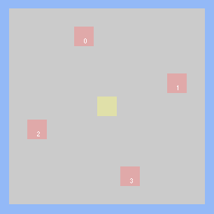
Historically, the sub-pixel location of MSAA sample points was totally out of your control as a programmer. Typically the hardware used rotated grid patterns such as this one, which were fixed for every pixel in your render target. For FEATURE_LEVEL_10_1, D3D added the concept of standard sample patterns that were required to be supported by the hardware. These were nice, in that you could specify the appropriate quality level and know exactly where the samples would be located. Without that, you either had to use shader intrinsics or resort to wackier methods for figuring out the sample positions. In theory it also gives you a very limited ability to control where sample points are located, but in practice the GPU vendors just made the standard multisample patterns the only patterns that they supported. So if you specified quality level 0, you got the same pattern as if you specified D3D11_STANDARD_MULTISAMPLE_PATTERN.
Fairly recently, we’ve finally seen the idea of programmable sample points getting some major attention. This has primarily came from Nvidia, who just added this functionality to their second-generation Maxwell architecture. You’ve probably seen some of the articles about their new “Multi-Frame Sampled Anti-Aliasing” (MFAA), which exploits the new hardware capabilities to jitter MSAA sample positions across alternating frames[1]1. The idea is that you can achieve a doubled effective sampling rate, as long as your resolve intelligently retrieves the subsamples from your previous frame. They also incorporate ideas from interleaved sampling, by varying their sample locations across a 2x2 quad instead of using the same pattern for all pixels. While the idea of yet-another control panel AA setting probably won’t do more than elicit some collective groans from the graphics community, it should at least get us thinking about what we might do if provided with full access to this new functionality for ourselves. And now that Nvidia has added an OpenGL extension as well as a corresponding D3D11 extension to their proprietary NVAPI, we can finally try out our own ideas (unless you work on consoles, in which case you may have been experimenting with them already!).
As for AMD, they’ve actually supported some form of programmable sample points since as far back as R600, at least if the command buffer documentation is accurate (look, for PA_SC_AA_SAMPLE_LOCS). Either way, Southern Islands certainly has support for varying sample locations across a 2x2 quad of pixels, which puts it on par with the functionality present in Maxwell 2.0. It’s a little strange to that AMD hasn’t done much to promote this functionality in the way that Nvidia has, considering they’ve had it for so long. Currently there’s no way to access this feature through D3D, but they have had an OpenGL extension for a long time now (thanks to Matthäus Chajdas and Graham Sellers for pointing out the extension!).
I’m not particularly knowledgeable about Intel GPU’s, and some quick searching didn’t return anything to indicate that they might be able to specify custom sample points. If anyone knows otherwise, then please let me know!
Update: Andrew Lauritzen has informed me via Twitter that Intel GPU’s do in fact support custom sample locations! Thank you again, Andrew!
How Does It Work?
Before we get into use cases, let’s quickly go over how to actually work with programmable sample points. Since I usually only use D3D when working on PC’s, I’m going to focus on the extensions for Maxwell GPU’s that were exposed in NVAPI. If you look in the NVAPI headers, you’ll find a function for creating an extended rasterizer state, with a corresponding description structure that has new members:
NvU32 ForcedSampleCount;
bool ProgrammableSamplePositionsEnable;
bool InterleavedSamplingEnable;
NvU8 SampleCount;
NvU8 SamplePositionsX[16];
NvU8 SamplePositionsY[16];
bool ConservativeRasterEnable;
NVAPI_QUAD_FILLMODE QuadFillMode;
bool PostZCoverageEnable;
bool CoverageToColorEnable;
NvU8 CoverageToColorRTIndex;
NvU32 reserved[16];
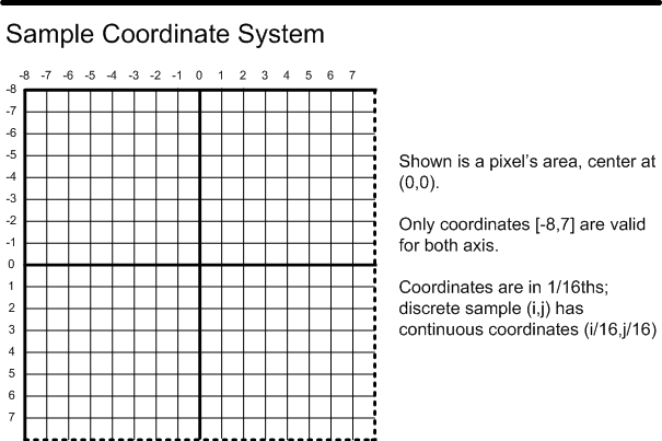
There’s a few other goodies in there (like conservative rasterization, and Post-Z coverage!), but the members that we’re concerned with are ProgrammableSamplePositionsEnable, InterleavedSamplingEnable, SampleCount, SamplePositionsX, and SamplePositionsY. ProgrammableSamplePositionsEnable is self-explanatory: it enables the functionality. SampleCount is also pretty obvious: it’s the MSAA sample count that we’re using for rendering. SamplePositionsX and SamplePositionsY are pretty clear in terms of what they’re used for: they’re for specifying the X and Y coordinates of our MSAA sample points. What’s not clear at all is how the API interprets those values. My initial guess was that they should contain 8-bit fixed point numbers where (0,0) is the top left of the pixel, and (255,255) is the bottom right. This was close, but not quite: they’re actually 4-bit fixed-point values that correspond to points in the D3D Sample Coordinate System. If you’re not familiar with this particular coordinate system (and you’re probably not), there’s a nice diagram in the documentation for the D3D11_STANDARD_MULTISAMPLE_QUALITY_LEVELS enumeration[2]2:
There’s also a bit more information in the documentation for EvaluateAttributeSnapped:
Only the least significant 4 bits of the first two components (U, V) of the pixel offset are used.
The conversion from the 4-bit fixed point to float is as follows (MSB...LSB),
where the MSB is both a part of the fraction and determines the sign:

1000 = -0.5f (-8 / 16)
1001 = -0.4375f (-7 / 16)
1010 = -0.375f (-6 / 16)
1011 = -0.3125f (-5 / 16)
1100 = -0.25f (-4 / 16)
1101 = -0.1875f (-3 / 16)
1110 = -0.125f (-2 / 16)
1111 = -0.0625f (-1 / 16)
0000 = 0.0f ( 0 / 16)
0001 = 0.0625f ( 1 / 16)
0010 = 0.125f ( 2 / 16)
0011 = 0.1875f ( 3 / 16)
0100 = 0.25f ( 4 / 16)
0101 = 0.3125f ( 5 / 16)
0110 = 0.375f ( 6 / 16)
0111 = 0.4375f ( 7 / 16)
So basically we have 16 buckets work with in X and Y, with the ability to have sample points sit on the top or left edges, but not on the bottom or right edges. Now as for the NVAPI extension, it uses this same coordinate system, except that all values or positive. This means that there is no sign bit, as in the values passed to EvaluateAttributeSnapped. Instead you can picture the coordinate system as ranging from 0 to 15, with 8 (0.5) corresponding to the center of the pixel:

Personally I like this coordinate system better, since having the pixel center at 0.5 is consistent with the coordinate system used for pixel shader positions and UV coordinates. It also means that going from a [0, 1] float to the fixed point representation is pretty simple:
rsDesc.SamplePositionsX[i] = uint8(Clamp(SamplePositions1x[i].x * 16.0f, 0.0f, 15.0f));
Now, what about that InterleavedSamplingEnable member that’s also part of the struct? This is a somewhat poorly-named parameter that controls whether you’re specifying the same sample positions for all 4 pixels in a 2x2 quad, or whether you’re specifying separate sample positions for each quad pixel. The API works such that the first N points correspond to the top left pixel, the next N correspond to the top right pixel, then the bottom left, followed by the bottom right. This means that for 2xMSAA you need to specify 8 coordinates, and for 4xMSAA you need to specify 16 coordinates. For 8xMSAA we would need to specify 32 coordinates, but unfortunately NVAPI only lets us specify 16 values. In this case, the 16 values correspond to the sample points in the top left and bottom left pixels of the quad.
Case Study: Low-Resolution Rendering
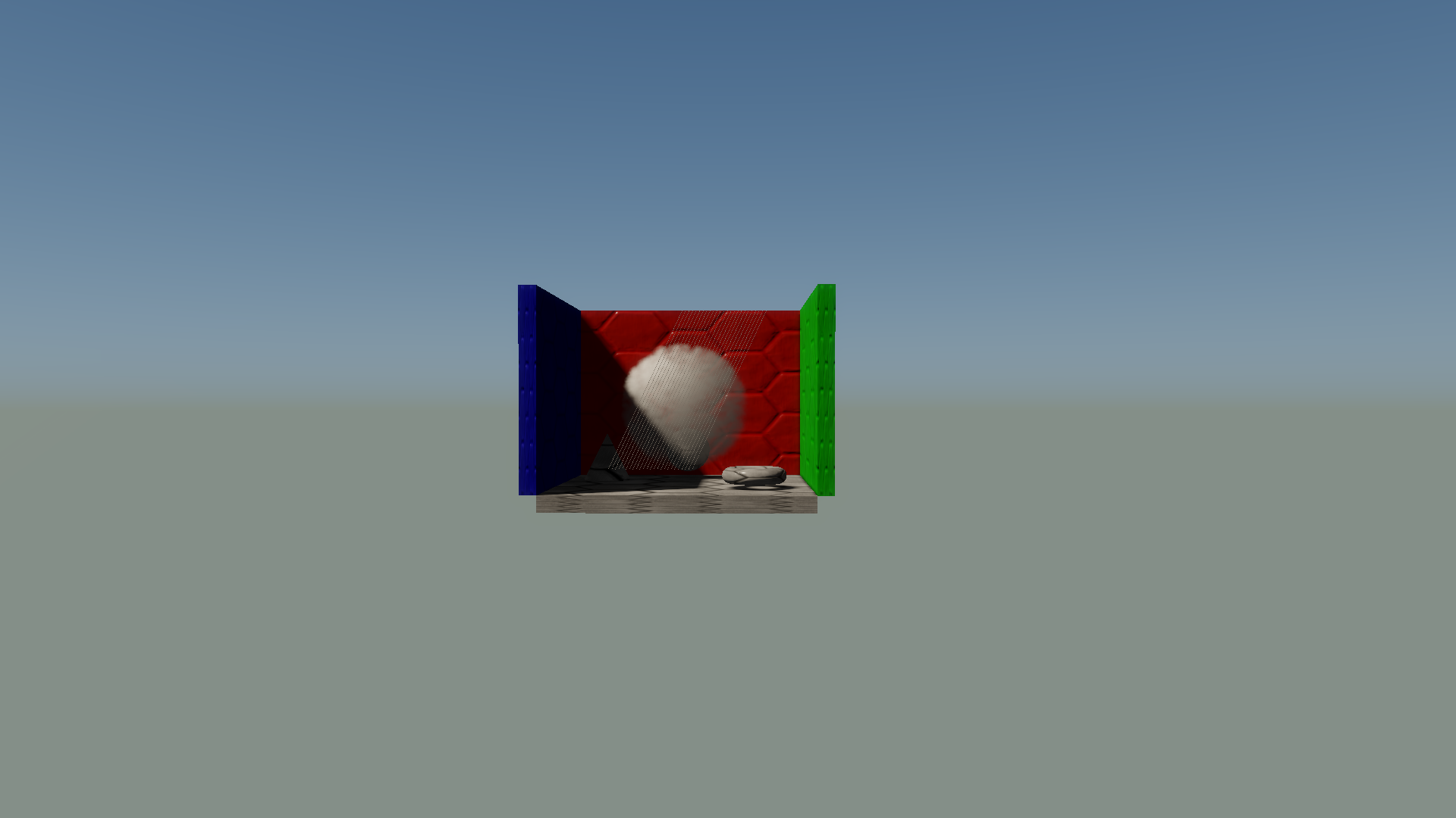
So now that we have programmable sample points, what exactly should we do with them? MFAA-style temporal jittering is a pretty obvious use case, but surely there’s other ways to make use of this functionality. One idea I’ve been kicking around has been to use MSAA as way to implement half-resolution rendering. Rendering particles at half resolution is really common in games, since blending many layers of particles can result in high costs from pixel shading and framebuffer operations. It can be an easy win in many cases, as long as the content you’re rendering won’t suffer too much from being shaded at half-rate and upsampled to full resolution. The main issue of course is that you can’t just naively upsample the result, since the half-resolution rasterization and depth testing will cause noticeably incorrect results around areas where the transparent geometry was occluded by opaque geometry. Here’s a comparison between half-resolution particle rendering with a naive bilinear upscale (left), and full-resolution rendering (right):

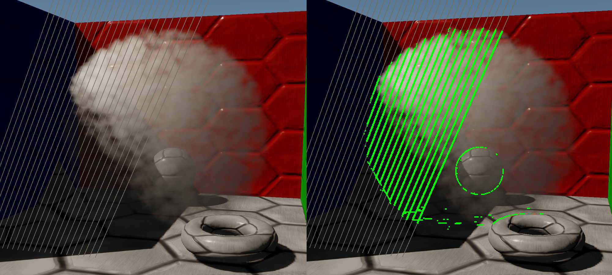
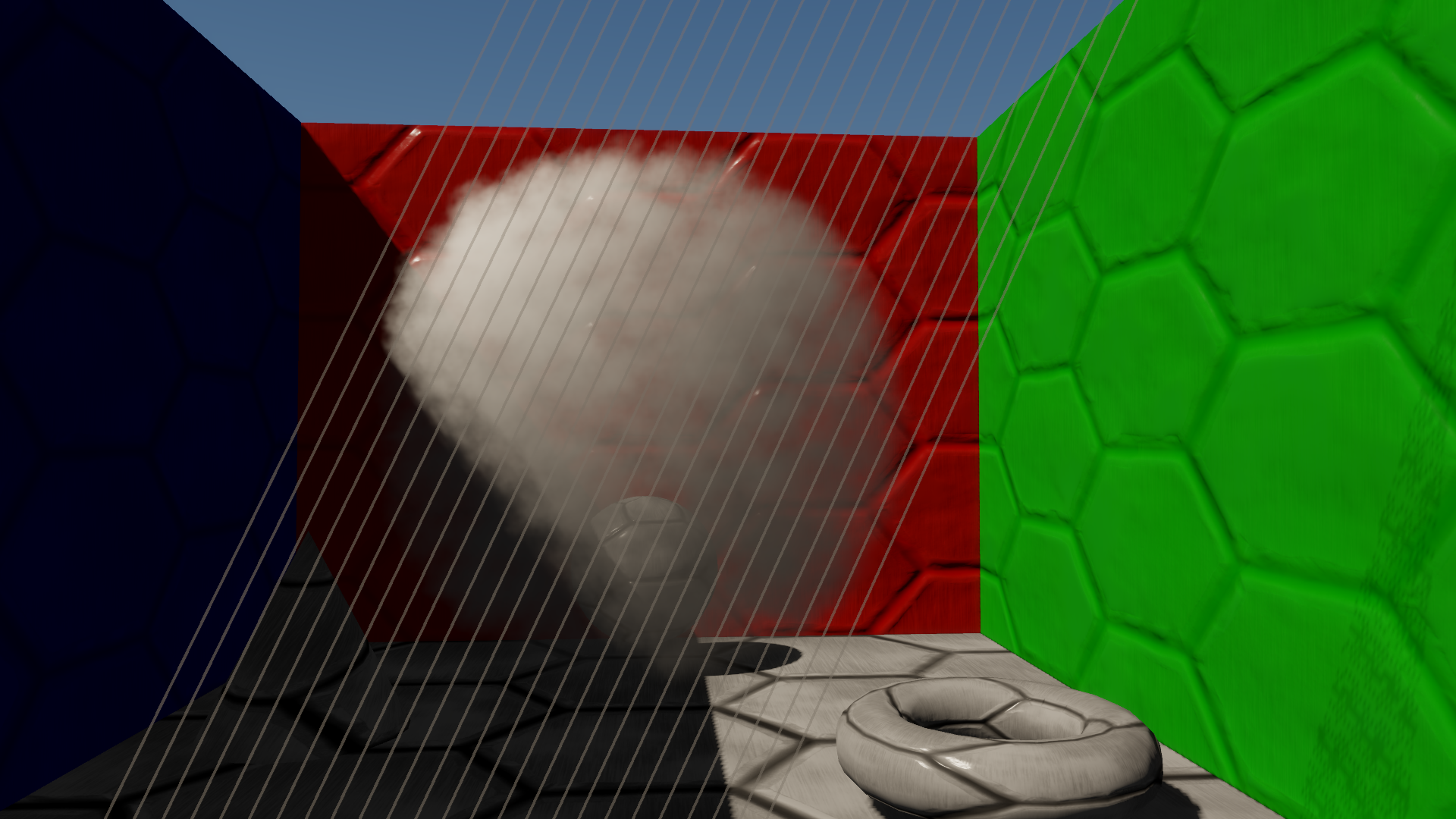
Notice how in some areas the low-resolution buffer has false occlusion, causing no particles to be visible for those pixels, while in other places the particles bleed onto the foreground geometry even though they should have been occluded. Perhaps the most obvious and common way to reduce these artifacts is to use some variation of a bilateral filter during the upscale, where the filtering weights are adjusted for pixels based on the difference between the low-resolution depth buffer and the full-resolution depth buffer. The idea behind doing this is that you’re going to have under or over-occlusion artifacts in places where the low-resolution depth is a poor representation of your full-resolution depth, and so you should reject low-resolution samples where the depth values are divergent. For The Order: 1886, we used a variant of this approach called nearest-depth upsampling, which was originally presented in an Nvidia SDK sample called OpacityMapping. This particular algorithm requires that you sample 4 low-resolution depth samples from a 2x2 bilinear footprint, and compare each one with the full-resolution depth value. If the depth values are all within a user-defined threshold, the low-resolution color target is bilinearly upsampled with no special weighting. However if any of the sample comparisons are greater than the treshold value, then the algorithm falls back to using only the low-resolution sample where the depth value was closest to the full-resolution depth value (hence the name “nearest-depth”). Overall the technique works pretty well, and in most cases it can avoid usual occlusion artifacts that are typical of low-resolution rendering. It can even be used in conjunction with MSAA, as long as you’re willing to run the filter for every subsample in the depth buffer. However it does have a few issues that we ran into over the course of development, and most of them stem from using depth buffer comparisons as a heuristic for occlusion changes in the transparent rendering. Before I list them, here’s an image that you can use to follow along (click for full resolution):
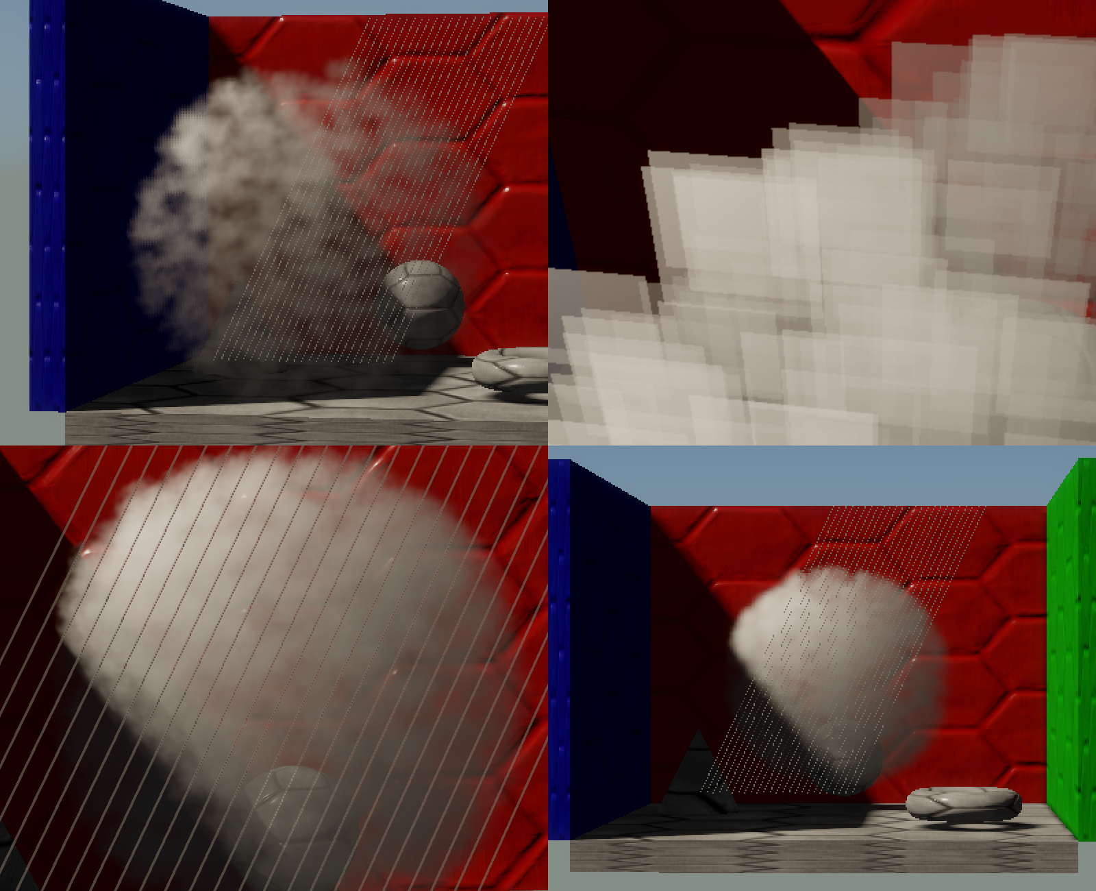
The first issue, illustrated in the top left corner, occurs when there are rapid changes in the depth buffer but no actual changes in the particle occlusion. In that image all of the particles are actually in front of the opaque geometry, and yet the nearest-depth algorithm still switches to point sampling due to depth buffer changes. It’s very noticeable in the pixels that overlap with the blue wall to the left. In this area there’s not even a discontinuity in the depth buffer, it’s just that the depth is changing quickly due to the oblique angle at which the wall is being viewed. The second issue, shown in the top right corner, is that the depth buffer contains no information about the actual edges of the triangles that were rasterized into the low-resolution render target. In this image I turned off the particle texture and disabled billboarding the quad towards the camera, and as a result you can clearly see the a blurry, half-resolution stair-step pattern at the quad edges. The third issue, shown in the bottom left, occurs when alpha-to-coverage is used to get sub-pixel transparency. In this image 2xMSAA is used, and the grid mesh (the grey parallel lines) is only being rendered to the first subsample, which was done by outputting a custom coverage mask from the pixel shader. This interacts poorly with the nearest-depth upsampling, since 1 of the 2 high-res samples won’t have the depth from the grid mesh. This causes blocky artifacts to occur for the second subsample. Finally, in the bottom right we have what was the most noticable issue for me personally: if the geometry is too small to be captured by the low-resolution depth buffer, then the upsample just fails completely. In practice this manifests as entire portions of the thin mesh “disappearing”, since they don’t correctly occlude the low-resolution transparents.
Ramble On
By now I hope you get the point: bilateral upsampling has issues for low resolution rendering. So how can we use MSAA and custom sampling points to do a better job? If you think about it, MSAA is actually perfect for what we want to accomplish: it causes the rasterizer and the depth test to run at a higher resolution than the render target(s), but the pixel shader still executes once per pixel. So if we use a half-resolution render target combined with 4x MSAA, then we should get exactly what we want: full-resolution coverage and depth testing, but half-resolution shading! This actually isn’t a new idea: Capcom tried a variant of this approach for the original Lost Planet on Xbox 360. For their implementation, which is outlined here in Japanese (English translation here), they were actually able to just alias their full-resolution render targets as a half-resolution 4xMSAA render targets while they were still in eDRAM. This worked for them, although at the time it was specific to the Xbox 360 hardware and also had no filtering applied to the low-resolution result (due to there being no explicit upscaling step). However we now have much more flexible GPU’s that give us generalized access to MSAA data, and my hunch was that we could improve upon this by using a more traditional “render in low-res and then upscale” approach. So I went ahead and implemented a sample program that demonstrates the technique, and so far it seems to actually work! I did have to work my way past a few issues, and so I’d like to go over the details in this article.
Here’s how the rendering steps were laid out every frame:
- Render Shadows
- Render Opaques (full res)
- Run pixel shader to convert from full-res depth to 4xMSAA depth
- Render particles at low-res with 4xMSAA, using ordered grid sample points
- Resolve low-res MSAA render target
- Upscale and composite low-res render target onto the full-res render target
The first two steps are completely normal, and don’t need explaining. For step #3, I used a full-screen pixel shader that only output SV_Depth, and executed at per-sample frequency. Its job was to look at the current subsample being shaded (provided by SV_SampleIndex), and use that to figure out which full-res depth pixel to sample from. The idea here is that 4 full-res depth samples need to be crammed into the 4 subsamples of the low-resolution depth buffer, so that all of the full-resolution depth values are fully represented in the low-res depth buffer:
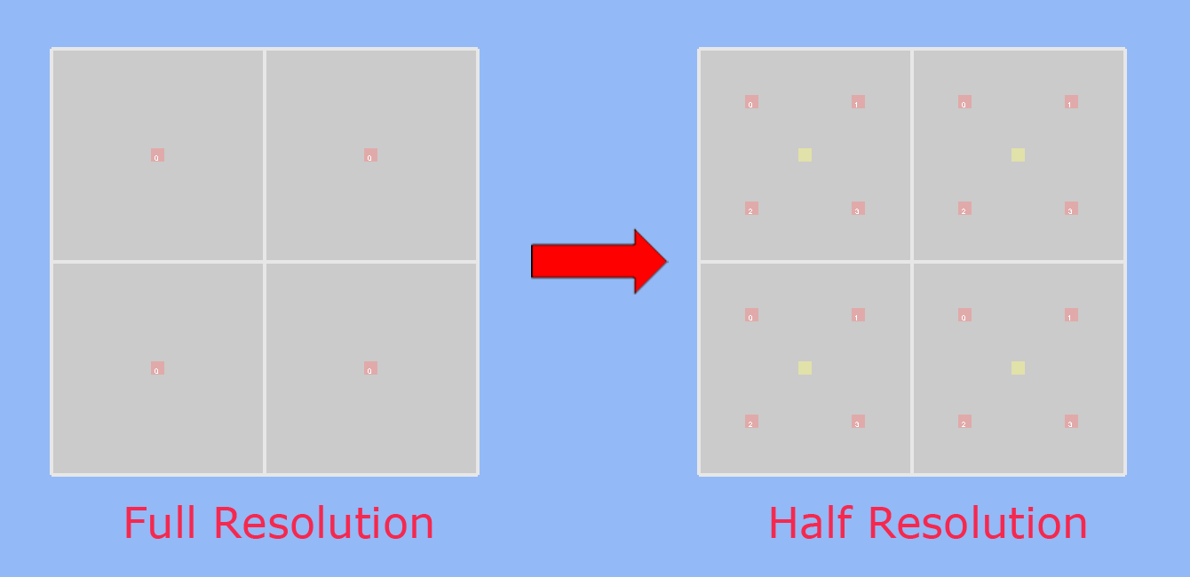
If you look at the image, you’ll notice that the MSAA sample positions in the low-resolution render target are spaced out in a uniform grid, instead of the typical rotated grid pattern. This is where programmable sample points come in: by manually specifying the sample points, we can make sure that the low-resolution MSAA samples correspond to the exact same location as they would be in the full-resolution render target. This is important if you want your low-resolution triangle edges to look the same as if they would if rasterized at full resolution, and also ensures correct depth testing at intersections with opaque geometry.
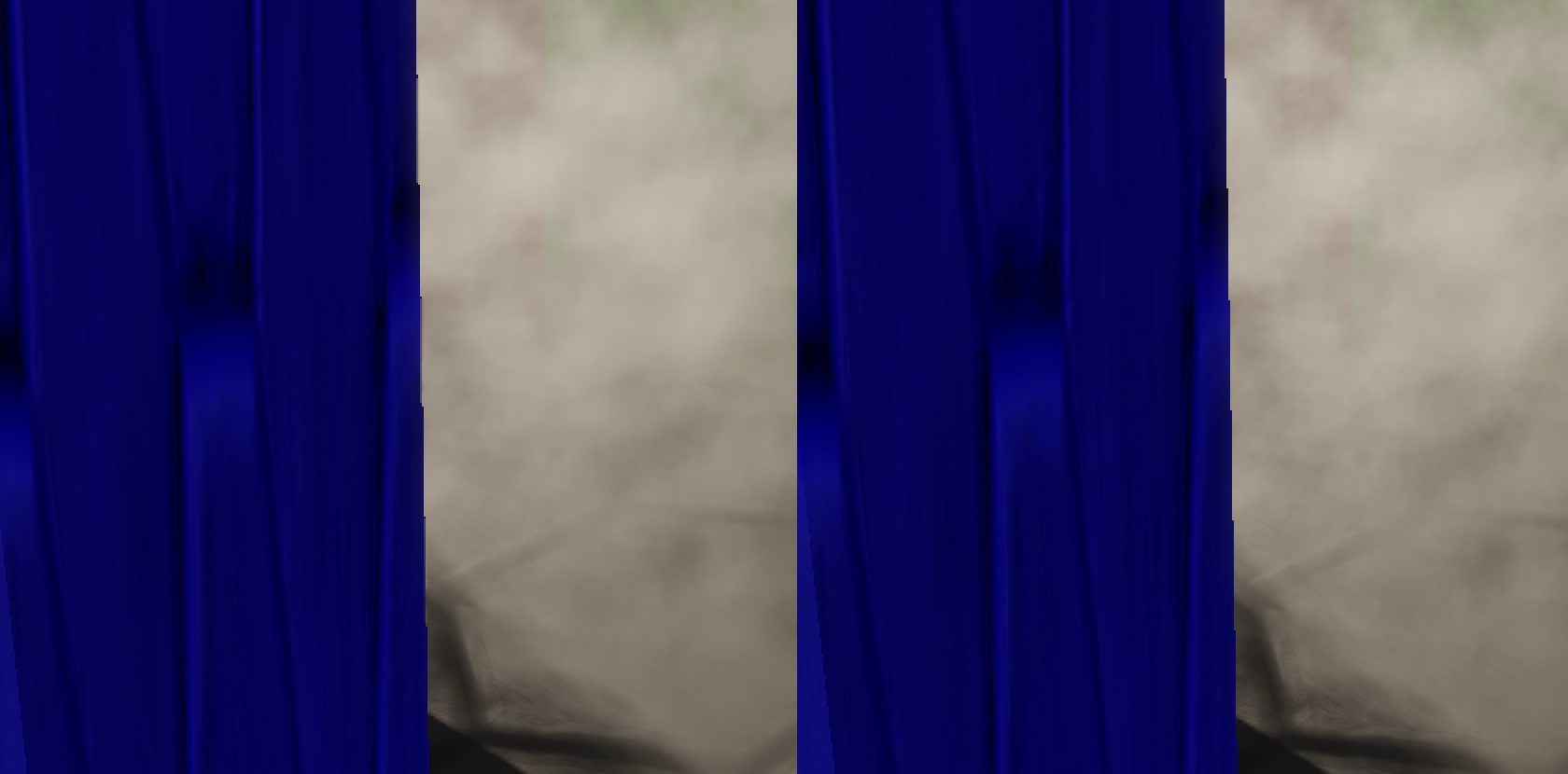
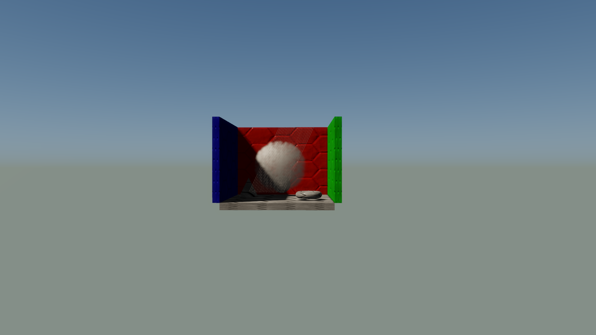
For step #4, we now render our transparent geometry to the half-resolution 4xMSAA render target. This is fairly straightforward, and in my implementation I just render a bunch of lit, billboarded particles with alpha blending. This is also where I apply the NVAPI rasterizer state containing the custom sample points, since this step is where rasterization and depth testing occurs. In my sample app you can toggle the programmable sample points on and off to see the effect (or rather, you can if you’re running on a GPU that supports it), although you probably wouldn’t notice anything with the default rendering settings. The issues are most noticable with albedo maps and billboarding disabled, which lets you see the triangle edges very clearly. If you look at pair of the images below, the image to left shows what happens when rasterizing with the 4x rotated grid pattern. The image on the right shows what it looks like when using our custom sample points, which are in a sub-pixel ordered grid pattern.
For step #5, I use a custom resolve shader instead of the standard hardware resolve. I did this so that I can look at the 4 subsamples, and find cases where the subsamples are not all the same. When this happens, this means that there was a sub-pixel edge during rasterization, that was either caused by a transparent triangle edge or by the depth test failing. For these pixels I output a special sentinel value of -FP16Max, so that the upscale/composite step has knowledge of the sub-pixel edge.
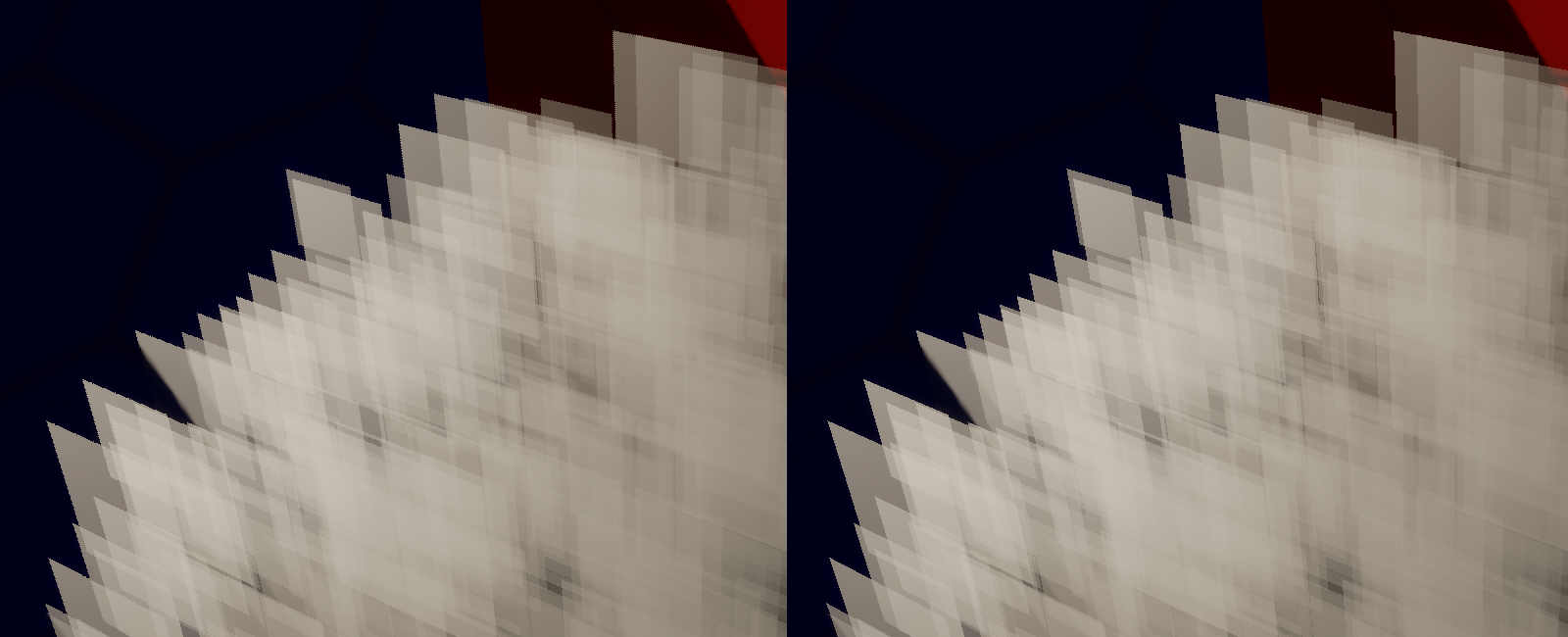
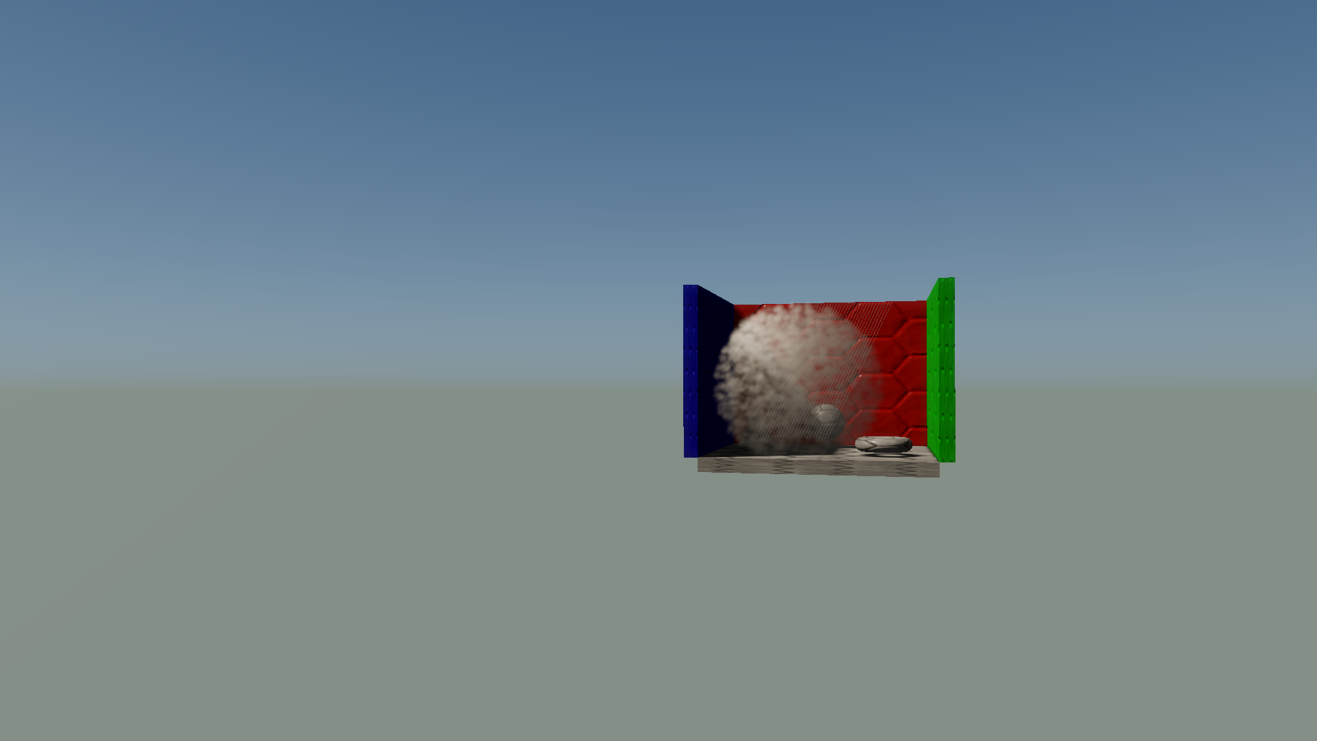
In the last step, I run another full-screen pixel shader that samples the low-resolution render target and blends it on top of the full-resolution render target. The important part of this step is choosing how exactly to filter when upsampling. If we just use plain bilinear filtering, the results will be smooth but the transparents will incorrectly bleed over onto occluding opaque pixels. If we instead use the MSAA render target and just load the single subsample that corresponds to the pixel being shaded, the results will look “blocky” due to the point sampling. So we must choose between filtering and point sampling, just as we did with nearest-depth upsampling. In the resolve step we already detected sub-pixel edges, and so we can already use that to determine when to switch to point sampling. This gets us most of the way there, but not all of the way. For bilinear filtering we’re going to sample a 2x2 neighborhood from the low-resolution texture, but our resolve step only detected edges within a single pixel. This means that if there’s an edge between two adjacent low-resolution pixels, then we’ll get a bleeding artifact if we sample across that edge. To show you what I mean, here’s an image showing low-resolution MSAA on the left, and full-resolution rendering on the right:
To detect this particular case, I decided to use an alpha comparison as a heuristic for changes in occlusion:
float4 msaaResult = LowResTextureMSAA.Load(lowResPos, lowResSampleIdx);
float4 filteredResult = LowResTexture.SampleLevel(LinearSampler, UV, 0.0f);
float4 result = filteredResult;
if(msaaResult.a - filteredResult.a > CompositeSubPixelThreshold)
    result = msaaResult;
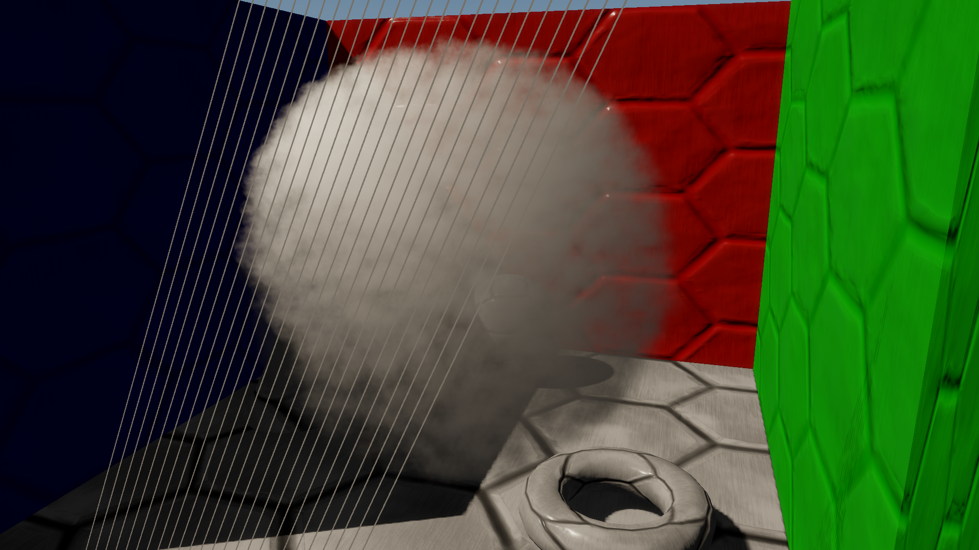
This worked out pretty nicely, since it essentially let me roll the two tests into one: if the resolve sub-pixel test failed then it would output -FP16Max, which automatically results in a very large difference during the edge test in the composite step. Here’s an image where the left side shows low-resolution MSAA rendering with the improved edge detection, and the right side shows the “edge” pixels by coloring them bright green:
Before I show some results and comparisons, I’d like to touch on integration with MSAA for full-resolution rendering. With nearest-depth upsampling, MSAA is typically handled by running the upsample algorithm for every MSAA sub-sample. This is pretty trivial to implement by running your pixel shader at per-sample frequency, which automatically happens if you use SV_SampleIndex as an input to your pixel shader. This works well for most cases, although it still doesn’t help situations where sub-pixel features are completely missing in the low-resolution depth buffer. For the low-resolution MSAA technique that I’m proposing it’s also fairly trivial to integrate with 2x MSAA: you simply need to use 8xMSAA for your low-resolution rendering, and adjust your sample points so that you have 4 sets of 2x rotated grid patterns. Then during the upsample you can execute the pixel shader at per-sample frequency, and run the alpha comparison for each full-resolution subsample. Unfortunately we can’t handle 4x so easily, since 16xMSAA is not available on any hardware that I know of. I haven’t given it a lot of thought yet, but I think it should be doable with some quality loss by performing a bit of bilateral upsampling during the compositing step. On consoles it should also be possible to use EQAA with 16x coverage samples to get a little more information during the upsampling.
Results
So now that we know that our MSAA trick can work for low-resolution rendering, how does it stack up against against techniques? In my sample app I also implemented full-resolution rendering as well as half-resolution with nearest-depth upsampling, and so we’ll use those as a basis for comparison. Full resolution is useful as a “ground truth” for quality comparisons, while nearest-depth upsampling is a good baseline for performance. So without further adieu, here are some links to comparison images:
Normal
Sub-Pixel Geo
Sub-Pixel Geo – 2x MSAA
Triangle Edges
High Depth Gradient
Alpha To Coverage
In my opinion, the quality is a consistent improvement over standard low-res rendering with a nearest-depth upscale. The low-resolution MSAA technique holds up in all of the failure cases that I mentioned earlier, and is still capable of providing filtered results in areas where the particles aren’t being occluded (unlike the Lost Planet approach, which essentially upsampled with point filtering).
To evaluate performance, I gathered some GPU timings for each rendering step on my GeForce GTX 970. The GPU time was measured using timestamp queries, and I recorded the maximum time interval from the past 64 frames. These were all gathered while rendering at 1920x1080 resolution (which means 960x540 for half-resolution rendering) with 16 * 1024 particles, and no MSAA:
| Render Mode | Depth Downscale | Particle Rendering | Resolve | Composite | Total |
|---|---|---|---|---|---|
| Full Res | N/A | 4.59ms | N/A | N/A | 4.59ms |
| Half Res – Nearest Depth | 0.04ms | 1.37ms | N/A | 0.31ms | 1.71ms |
| Half Res - MSAA | 0.13ms | 1.48ms | 0.23ms | 0.08ms | 1.92ms |
On my hardware, the low-resolution MSAA technique holds up fairly well against the baseline of half-res with nearest depth upsampling. The resolve adds a bit of time, although that particular timestamp was rather erratic and so I’m not 100% certain of its accuracy. One nice thing is that the composite step is now cheaper, since the shader is quite a bit simpler. In the interest of making sure that all of my cards are on the table, one thing that I should mention is that the particles in this sample don’t sample the depth buffer in the pixel shader. This is common for implementing soft particles as well as for computing volumetric effects by marching along the view ray. In these cases the pixel shader performance would likely suffer if it had to point sample an MSAA depth buffer, and so it would probably make sense to prepare a 1x depth buffer during the downscale phase. This would add some additional cost to the low-resolution MSAA technique, and so I should probably consider adding it to the sample at some point.
These numbers were gathered with 2xMSAA used for full-resolution rendering:
| Render Mode | Depth Downscale | Particle Rendering | Resolve | Composite | Total |
|---|---|---|---|---|---|
| Full Res | N/A | 4.69ms | N/A | N/A | 4.69ms |
| Half Res – Nearest Depth | 0.06ms | 1.40ms | N/A | 0.38ms | 1.81ms |
| Half Res - MSAA | 0.25ms | 2.11ms | 0.24ms | 0.17ms | 1.74ms |
Unfortunately the low-resolution MSAA technique doesn’t hold up quite as well in this case. The particle rendering gets quite a bit more expensive, and the cost of downscale as well as the composite both increase. It does seem odd for the rendering cost to increase so much, and I’m not sure that I can properly explain it. Perhaps there is a performance cliff when going from 4x to 8x MSAA on my particular GPU, or maybe there’s a bug in my implementation.
Bring It On Home
So what conclusions can we draw from all of this? At the very least, I would say that programmable sample points can certainly be useful, and that low-resolution MSAA is a potentially viable use case for the functionality. In hindsight it seems that my particular implementation isn’t necessarily the best way to show off the improvement that you get from using programmable sample points, since the alpha-blended particles don’t have any noticeable triangle edges by default. However it’s definitely relevant if you want to consider more general transparent geometry, or perhaps even rendering opaque geometry at half resolution. Either way, I would really like to see broader support for the functionality being exposed in PC API’s. Unfortunately it’s not part of any Direct3D 12 feature set, so we’re currently stuck with Nvidia’s D3D11 or OpenGL extensions. It would be really great to see it get added to a future D3D12 revision, and have it be supported across Nvidia, Intel, and AMD hardware. Until that happens I suspect it will mostly get used by console developers.
Update: programmable sample point functionality was added to D3D12!
If you would like to check out the code for yourself, I’ve posted it all on GitHub. If you’d just like to download and run the pre-compiled executable, I’ve also made a binary release available for download. If you look through the build instructions, you’ll notice that I didn’t include the NVAPI headers and libs in the repository. I made this choice because of the ominous-sounding license terms that are included in the header files, as well as the agreement that you need to accept before downloading it. This means that the code won’t compile by default unless you download NVAPI yourself, and place it in the appropriate directory. However if you just want to build it right away, there’s a preprocessor macro called “UseNVAPI_” at the top of LowResRendering.cpp that you can set to 0. If you do that then it won’t link against NVAPI, and the app will build without it. Of course if you do this, then you won’t be able to use the programmable sample point feature in the sample app. The feature will also be disabled if you aren’t running on a Maxwell 2.0 (or newer) Nvidia GPU, although everything else should work correctly on any hardware that supports FEATURE_LEVEL_11_0. Unfortunately I don’t have any non-Nvidia hardware to test on, so please let me know if you run into any issues.
References
[1] D3D11_STANDARD_MULTISAMPLE_QUALITY_LEVELS enumeration
[2] MSDN documentation for EvaluateAttributeSnapped
[3] Multi-Frame Samples Anti-Aliasing (MFAA)
[4] Interleaved Sampling
[5] GL_NV_sample_locations
[6] NVAPI
[7] Hybrid Reconstruction Anti-Aliasing
[8] GPU-Driven Rendering Pipelines
[9] AMD R600 3D Registers
[10] AMD Southern Islands 3D Registers
[11] AMD_sample_positions
[12] OpacityMapping White Paper
[13] High-Speed, Off-Screen Particles (GPU Gems 3)
[14] Lost Planet Tech Overview (english translation)
[15] Mixed Resolution Rendering
[16] Destiny: From Mythic Science Fiction to Rendering in Real-Time
Comments:
Thanks for the post, very interesting! Cool that you covered use case for particles (description of temporal sample varying regular AA was done by Michal Drobot in his HRAA presentation). Can you answer if you used this on The Order 1886 (you mentioned during your Siggraph talk some console specific, NDA details), or is it all NDA’d? I have a question about mention of soft particles and proposed solution: “In these cases the pixel shader performance would likely suffer if it had to point sample an MSAA depth buffer, and so it would probably make sense to prepare a 1x depth buffer during the downscale phase.” - I don’t really understand what is this 1x depth buffer - regular full res buffer? Average depth buffer (reintroducing aliasing)? In any case it seems to me that soft particles have to run PS per subsample to get proper transparency ratio, or otherwise will reintroduce half res edges, do I understand correctly? Thanks again for the write up! BTW. picture msaaedges.png is not clickable like others - this is not a problem, but seems like it wasn’t intended.
#### []( "") -
Why resolve at all? With 4xMSAA, you have 4 color samples per low-res pixel, corresponding to the full-res pixel centers. Why throw them away, only to reconstruct during composite? I must be missing something.
#### [MJP](http://mynameismjp.wordpress.com/ "mpettineo@gmail.com") -
Hi Bart! Good to hear from you! I didn’t use any of these techniques for The Order. After the game shipped I did integrate my own form of subsample jittering, so if that continues to work out then we will probably use it for the next project. Regarding the soft particles, I was suggesting to just use a point sampled 1/2 res depth buffer. Initially I had thought that it would be possible okay to do this as long as the fade was restricted to pixels that were in front of the opaque depth buffer value, but I thought about it some more and I realized that it would that this would still result in artifacts. So at the moment I don’t have a good solution for handling soft particles or volumetrics, which is a really big downside. I’ll have to think about it some more, and perhaps I can come up with approach that doesn’t degenerate to shading for each subsample. Thank you for pointing out the missing link, it should be fixed now! @Anonymous - I don’t “throw away” the subsamples, I still use them during the composite. The resolve step is to allow for bilinear filtering during the composite. If you just used the subsamples without filtering, you get correct edges but the result will look very “blocky” due to the point sampling (basically you get the same result as Lost Planet). But if you resolve the texture, then you can use bilinear filtering (or some other filter kernel) during the upscale in order to get better-looking results. Technically you could skip the resolve, and during the composite you could filter loading all subsamples for each pixel in the 2x2 filter footprint. But this would require 16 texture samples instead of just 1.
#### [AGraphicsGuy](http://agraphicsguy.wordpress.com "jerrycao_1985@icloud.com") -
Great blog. Just a heads-up, you can actually add ‘read more tag’ after the first couple of paragraphs so that only part of your blog will be visible in the main page, instead of the full article.
#### [Beware of SV_Coverage – Yosoygames](http://www.yosoygames.com.ar/wp/2017/02/beware-of-sv_coverage/ "") -
[…] been obvious). Neither GL spec, docs, MSDN docs and other readings warned me about these gotchas. MJP’s blogposts were very useful, but that’s it. And they weren’t very specific to […]
-
Some of you might remember ATI’s old “Temporal AA” feature from their Catalyst Control Panel, which had a similar approach to MFAA in that it alternated sample patterns every frame. However unlike MFAA, it just relied on display persistance to combine samples from adjacent frames, instead of explicitly combining them in a shader. ↩︎
-
If you’ve been working with D3D11 for a long time and you don’t recognize these diagrams, you’re not going crazy. The original version of the D3D11 docs were completely missing all of this information, which actually made the “standard” MSAA patterns somewhat useless. This is what the docs for D3D11_STANDARD_MULTISAMPLE_QUALITY_LEVELS look like in the old DirectX SDK documentation, and this is what EvaluateAttributeSnapped looked like. ↩︎