A Sampling of Shadow Techniques
A little over a year ago I was looking to overhaul our shadow rendering at work in order to improve overall quality, as well as simplify the workflow for the lighting artists (tweaking biases all day isn’t fun for anybody). After doing yet another round of research into modern shadow mapping techniques, I decided to do what I usually do and starting working on sample project that I could use as a platform for experimentation and comparison. And so I did just that. I had always intended to put it on the blog, since I thought it was likely that other people would be evaluating some of the same techniques as they upgrade their engines for next-gen consoles. But I was a bit lazy about cleaning it up (there was a lot of code!), and it wasn’t the most exciting thing that I was working on, so it sort-of fell by the wayside. Fast forward to a year later, and I found myself looking for a testbed for some major changes that I was planning for the settings and UI portion of my sample framework. My shadows sample came to mind since it was chock-full of settings, and that lead me to finally clean it up and get it ready for sharing. So here it is: (and now on GitHub!)
https://github.com/TheRealMJP/Shadows
If you head to the releases page, there’s a zip file containing all of the code and content as well as a pre-compiled executable. Note that I’ve fully switched over to VS 2012 now, so you’ll need it to open the project and compile the code. If you don’t have it installed, then you may need to download and install the VC++ 2012 Redistributable in order to run the pre-compiled binary.
-
Update 9/12/2013
- Fixed a bug with cascade stabilization behaving incorrectly for very small partitions
- Restore previous min/max cascade depth when disabling Auto-Compute Depth Bounds
- Thanks to Stephen Hill for pointing out the issues!
-
Update 9/18/2013
- Ignacio Castaño was kind enough to share the PCF technique being used in The Witness, which he integrated into the sample under the name “OptimizedPCF”. Thanks Ignacio!
-
Update 11/3/2013
- Fixed SettingsCompiler string formatting issues for non-US cultures
-
Update 2/17/2015
- Fixed VSM/EVSM filtering shader that was broken with latest Nvidia drivers
- Added Moment Shadow Mapping
- Added notes about biasing VSM, EVSM, and MSM
-
Update 1/23/2016
- Fixed incorrect maximum exponent for 16-bit EVSM (thank you Christoph!)
- Compile the main pixel shader on-demand so that all shader permutations don’t need to be compiled and loaded up-front
- Uploaded the project to GitHub
-
Update 2/26/2023
- Added the section about disabling Z clipping
The sample project is set up as a typical “cascaded shadow map from a directional light” scenario, in the same vein as the CascadedShadowMaps11 sample from the old DX SDK or the more recent Sample Distribution Shadow Maps sample from Intel. In fact I even use the same Powerplant scene from both samples, although I also added in human-sized model so that you can get a rough idea of how well the shadowing looks on characters (which can be fairly important if you want your shadows to look good in cutscenes without having to go crazy with character-specific lights and shadows). The basic cascade rendering and setup is pretty similar to the Intel sample: a single “global” shadow matrix is created every frame based on the light direction and current camera position/orientation, using an orthographic projection with width, height, and depth equal to 1.0. Then for each cascade a projection is created that’s fit to the cascade, which is used for rendering geometry to the shadow map. For sampling the cascade, the projection is described as a 3D scale and offset that’s applied to the UV space of the “global” shadow projection. That way you just use one matrix in the shader to calculate shadow map UV coordinates + depth, and then apply the scale and offset to compute the UV coordinates + depth for the cascade that you want to sample. Unlike the Intel sample I didn’t use any kind of deferred rendering, so I decided to just fix the number of cascades at 4 instead of making it tweakable at runtime.
Cascade Optimization
Optimizing how you fit your cascades to your scene and current viewpoint is pretty crucial for reducing perspective aliasing and the artifacts that it causes. The old-school way of doing this for CSM is to chop up your entire visible depth range into N slices using some sort of partitioning scheme (logarithmic, linear, mixed, manual, etc.). Then for each slice of the view frustum, you’d tightly fit an AABB to the slice and use that as the parameters for your orthographic projection for that slice. This gives you the most optimal effective resolution for a given cascade partition, however with 2006-era shadow map sizes you still generally end up with an effective resolution that’s pretty low relative to the screen resolution. Combine this with 2006-era filtering (2x2 PCF in a lot of cases), and you end up with quite a bit of aliasing. This aliasing was exceptionally bad, due to the fact that your cascade projections will translate and scale as your camera moves and rotates, which results in rasterization sample points changing from frame to frame as the camera moves. The end result was crawling shadow edges, even from static geometry. The most popular solution for this problem was to trade some effective shadow map resolution for stable sample points that don’t move from frame to frame. This was first proposed (to my knowledge) by Michal Valient in his ShaderX6 article entitled “Stable Cascaded Shadow Maps”. The basic idea is that instead of tightly mapping your orthographic projection to your cascade split, you map it in such a way that the projection won’t change as the camera rotates. The way that Michal did it was to fit a sphere to the entire 3D frustum split and then fit the projection to that sphere, but you could do it any way that gives you a consistent projection size. To handle the translation issue, the projections are “snapped” to texel-sized increments so that you don’t get sub-texel sample movement. This ends up working really well, provided that your cascade partitions never change (which means that changing your FOV or near/car clip planes can cause issues). In general the stability ends up being a net win despite the reduced effective shadow map resolution, however small features and dynamic objects end up suffering.
2 years ago Andrew Lauritzen gave a talk on what he called “Sample Distribution Shadow Maps”, and released the sample that I mentioned earlier. He proposed that instead of stabilizing the cascades, we could instead focus on reducing wasted resolution in the shadow map to a point where effective resolution is high enough to give us sub-pixel resolution when sampling the shadow map. If you can do that then you don’t really need to worry about your projection changing frame to frame, provided that you use decent filtering when sampling the shadow map. The way that he proposed to do this was to analyze the depth buffer generated for the current viewpoint, and use it to automatically generate an optimal partitioning for the cascades. He tried a few complicated ways of achieving this that involved generating a depth histogram on the GPU, but also proposed a much more practical scheme that simply computed the min and max depth values. Once you have the min and max depth, you can very easily use that to clamp your cascades to the subset of your depth range that actually contains visible pixels. This might not sound like a big deal, but in practice it can give you huge improvements. The min Z in particular allows you to have a much more optimal partitioning, which you can get by using an “ideal” logarithmic partitioning scheme. The main downside is that you need to use the depth buffer, which puts you in the awful position of having the CPU dependent on results from the GPU if you want to do your shadow setup and scene submission on the CPU. In the sample code they simply stall and readback the reduction results, which isn’t really optimal at all in terms of performance. When you do something like this the CPU ends up waiting around for the driver to kick off commands to the GPU and for the GPU to finish processing them, and then you get a stall on the GPU while it sits around and waits for the CPU to start kicking off commands again. You can potentially get around this by doing what you normally do for queries and such, and deferring the readback for one or more frames. That way the results are (hopefully) already ready for readback, and so you don’t get any stalls. But this can cause you problems, since the cascades will trail a frame behind what’s actually on screen. So for instance if the camera moves towards an object, the min Z may not be low enough to fit all of the pixels in the first cascade and you’ll get artifacts. One potential workaround is to use the previous frame’s camera parameters to try to predict what the depth of a pixel will be for the next frame based on the instantaneous linear velocity of the camera, so that when you retrieve your min/max depth a frame late it actually contains the correct results. I’ve actually done this in the past (but not for this sample, I got lazy) and it works as long as long as the camera motion stays constant. However it won’t handle moving objects unless you store the per-pixel velocity with regards to depth and factor that into your calculations. The ultimate solution is to do all of the setup and submission on the GPU, but I’ll talk about that in detail later on.
These are the options implemented in the sample that affect cascade optimization:
- Stabilize Cascades - enables cascade stabilization using the method from ShaderX6.
- Auto-Compute Depth Bounds - computes the min and max Z on the GPU, and uses it to tightly fit the cascades as in SDSM.
- Readback Latency - number of frames to wait for the depth reduction results
- Min Cascade Distance/Max Cascade Distance - manual min and max Z when Auto-Compute Depth Bounds isn’t being used
- Partition Mode - can be Logarithmic, PSSM (mix between linear and logarithmic), or manual
- Split Distance 0/Split Distance 1/Split Distance 2/Split Distance 3 - manual partition depths
- PSSM Lambda - mix between linear and logarithmic partitioning when PartitionMode is PSSM
- Visualize Cascades - colors pixels based on which cascade they select
Shadow Filtering
Shadow map filtering is the other important aspect of reducing artifacts. Generally it’s needed to reduce aliasing due to undersampling the geometry being rasterized into the shadow map, but it’s also useful for cases where the shadow map itself is being undersampled by the pixel shader. The most common technique for a long time has been Percentage Closer Filtering (PCF), which basically amounts to sampling a normal shadow map, performing the shadow comparison, and then filtering the result of that comparison. Nvidia hardware has been able to do a 2x2 bilinear PCF kernel in hardware since…forever, and it’s required of all DX10-capable hardware. Just about every PS3 game takes advantage of this feature, and Xbox 360 games would too if the GPU supported it. In general you see lots of 2x2 or 3x3 grid-shaped PCF kernels with either a box filter or a triangle filter. A few games (notably the Crysis games) use a randomized sample pattern with sample points located on a disc, which trades regular aliasing for noise. With DX11 hardware there’s support for GatherCmp, which essentially gives you the results of 4 shadow comparisons performed for the relevant 2x2 group of texels. With this you can efficiently implement large (7x7 or even 9x9) filter kernels with minimal fetch instructions, and still use arbitrary filter kernels. In fact there was an article in GPU Pro called “Fast Conventional Shadow Filtering” by Holger Gruen, that did exactly this, and even provided source code. It can be stupidly fast…in my sample app going from 2x2 PCF to 7x7 PCF only adds about 0.4ms when rendering at 1920x1080 on my AMD 7950. For comparison, a normal grid sampling approach adds about 2-3ms in my sample app for the maximum level of filtering. The big disadvantage to the fixed kernel modes is that they rely on the compiler to unroll the loops, which make for some sloooowwww compile times. The sample app uses a compilation cache so you won’t notice it if you just start it up, but without the cache you’ll see it takes quite while due to the many shader permutations being used. For that reason I decided to stick with a single kernel shape (disc) rather than using all of the shapes from the GPU Pro article, since compilation times were already bad enough.
So far the only real competitor to gain any traction in games is Variance Shadow Maps (VSM). I won’t go deep into the specifics since the original paper and GPU Gems article do a great job of explaining it. But the basic gist is that you work in terms of the mean and variance of a distribution of depth values at a certain texel, and then use use that distribution to estimate the probability of a pixel being in shadow. The end result is that you gain the ability to filter the shadow map without having to perform a comparison, which means that you can use hardware filtering (including mipmaps, anistropy or even MSAA) and that you can pre-filter the shadow map with standard “full-screen” blur pass. Another important aspect is that you generally don’t suffer from the same biasing issues that you do with PCF. There’s some issues of performance and memory, since you now need to store 2 high-precision values in your shadow map instead of just 1. But in general the biggest problem is the light bleeding, which occurs when there’s a large depth range between occluders and receivers. Lauritzen attempted to address this a few years later by applying an exponential warp to the depth values stored in the shadow map, and performing the filtering in log space. It’s generally quite effective, but it requires high-precision floating point storage to accommodate the warping. For maximum quality he also proposed storing a negative term, which requires an extra 2 components in the shadow map. In total that makes for 4x FP32 components per texel, which is definitely not light in terms of bandwidth! However you could say that it arguably produces the highest-quality results, and it does so without having to muck around with biasing. This is especially true when pre-filtering, MSAA, anisotropic filtering, and mipmaps are all used, although each of those brings about additional cost. To provide some real numbers, using EVSM4 with 2048x2048 cascades, 4xMSAA, mipmaps, 8xAF, and highest-level filtering (9 texels wide for the first cascade), adds about 11.5ms relative to a 7x7 fixed PCF kernel. A more reasonable approach would be to go with 1024x1024 shadow maps with 4xMSAA, which is around 3ms slower than the PCF version.
These are the shadow filtering modes that are implemented:
- FixedSizePCF - optimized GatherCmp PCF with disc-shaped kernel
- GridPCF - manual grid-based PCF sampling using NxN samples
- RandomDiscPCF - randomized samples on a Poisson disc, with optional per-pixel randomized rotation
- OptimizedPCF - similar to FixedSizePCF, but uses bilinear PCF samples to implement a uniform filter kernel.
- VSM - variance shadow maps
- EVSM2 - exponential variance shadow maps, positive term only
- EVSM4 - exponential variance shadow maps, both positive and negative terms
- MSM Hamburger - moment shadow mapping, using the “Hamburger 4MSM” technique from the paper.
- MSM Hausdorff - moment shadow mapping, using the “Hausdorff 4MSM” technique from the paper
Here’s the options available in my sample related to filtering:
- Shadow Mode - the shadow filtering mode, can be one of the above values
- Fixed Filter Size - the kernel width in texels for the FixedSizePCF mode, can be 2x2 though 9x9
- Filter Size - the kernel width in fractional world space units for all other filtering modes. For the VSM modes, it’s used in a pre-filtering pass.
- Filter Across Cascades - blends between two cascade results at cascade boundaries to hide the transition
- Num Disc Samples - number of samples to use for RandomDiscPCF mode
- Randomize Disc Offsets - if enabled, applies a per-pixel randomized rotation to the disc samples
- Shadow MSAA - MSAA level to use for VSM, EVSM, and MSM modes
- VSM/MSM Format - the precision to use for VSM, EVSM, and MSM shadow maps. Can be 16bit or 32bit . For VSM the textures will use a UNORM format, for EVSM they will be FLOAT. For the MSM 16-bit version, the optimized quantization scheme from the paper is used to store the data in UNORM texture.
- Shadow Anisotropy - anisotropic filtering level to use for VSM, EVSM, and MSM
- Enable Shadow Mips - enables mipmap generation and sampling for VSM, EVSM, and MSM
- Positive Exponent/Negative Exponent - the exponential warping factors for the positive and negative components of EVSM
- Light Bleeding Reduction - reduces light bleeding for VSM/EVSM/MSM, but results in over-darkening
In general I try to keep the filtering kernel fixed in world space across each cascade by adjusting the kernel width based on the cascade size. The one exception is the FixedSizePCF mode, which uses the same size kernel for all cascades. I did this because I didn’t think that branching over the fixed kernels would be a great idea. Matching the filter kernel for each cascade is nice because it helps hide the seams at cascade transitions, which means you don’t have to try to filter across adjacent cascades in order to hide them. It also means that you don’t have to use wider kernels on more distant pixels, although this can sometimes lead to visible aliasing on distant surfaces.
I didn’t put a whole lot of effort into the “RandomDiscPCF” mode, so it doesn’t produce optimal results. The randomization is done per-pixel, which isn’t great since you can clearly see the random pattern tiling over the screen as the camera moves. For a better comparison you would probably want to do something similar to what Crytek does, and tile a (stable) pattern over each cascade in shadowmap space.
Biasing
When using conventional PCF filtering, biasing is essential for avoiding “shadow acne” artifacts. Unfortunately, it’s usually pretty tricky to get it right across different scenes and lighting scenarios. Just a bit too much bias will end up killing shadows entirely for small features, which can cause characters too look very bad. My sample app exposes 3 kinds of biasing: manual depth offset, manual normal-based offset, and automatic depth offset based on receiver slope. The manual depth offset, called simply Bias in the UI, simply subtracts a value from the pixel depth used to compare against the shadow map depth. Since the shadow map depth is a [0, 1] value that’s normalized to the depth range of the cascade, the bias value represents a variable size in world space for each cascade. The normal-based offset, called Offset Scale in the UI, is based on “Normal Offset Shadows”, which was a poster presented at GDC 2011. The basic idea is you actually create a new virtual shadow receiver position by offsetting from the actual pixel position in the direction of the normal. The trick is that you offset more when the surface normal is more perpendicular to the light direction. Angelo Pesce has a hand-drawn diagram explaining the same basic premise on his blog, if you’re having trouble picturing it.. This technique can actually produce decent results, especially given how cheap it is. However since you’re offsetting the receiver position, you actually “move” the shadows a bit which is a bit weird to see as you tweak the value. Since the offset is a world-space distance, in my sample I scale it based on the depth range of the cascade in order to make it consistent across cascade boundaries. If you want to try using it, I recommend starting with a small manual bias of 0.0015 or so and then slowly increasing the Offset Scale to about 1.0 or 2.0. Finally we have the automatic solution, where we attempt to compute the “perfect” bias amount based on the slope of the receiver. This setting is called Use Receiver Plane Depth Bias in the sample. To determine the slope, screen-space derivatives are used in the pixel shader. When it works, it’s fantastic. However it will still run into degenerate cases where it can produce unpredictable results, which is something that often happens when working with screen-space derivatives.
There are also separate biasing parameters for VSM and MSM techniques. The “VSM Bias” affects VSM and EVSM, while “MSM Depth Bias” and “MSM Moment Bias” are used for MSM. For VSM and 32-bit EVSM, a bias value of 0.01 (which corresponds to an actual value of 0.0001) is sufficent. However for 16-bit EVSM a bias of up to 0.5 (0.005) is required to alleviate precision issues. For only the moment bias is particularly relevent. This value needs to be at least 0.001-0.003 (0.000001-0.000003) for 32-bit modes, while the quantized 16-bit mode requires a higher bias of around 0.03 (0.00003). Note that for both EVSM and MSM increasing the bias can also increase the amount of visible light bleeding.
Disabling Z Clipping
Shadow maps for directional lights have an interesting problem due to the light source being considered infinitely far away: this means that occluders can also cast shadows for an infinite distance. For a typical cascaded shadow map implementation each cascade will rasterize shadows using an orthgraphic frustum (which is an OBB in world space) that’s aligned with the light direction, and where the far clip plane extends just enough to enclose the primary view frustum. But what about the near clip plane for rasterizing that cascade? We can’t just pull that infinitely far back towards the directional light, and even if we could we wouldn’t want to because we would have terrible depth buffer precision. Meanwhile if we just make the near clip enclose the main view frustum like we did for the far clip plane, we would clip away occluders that are not currently visible but do cast shadows onto visible surfaces. It turns out there’s a trick we can use for this specific case: we can simply disable Z clipping, in which case triangles in front of the near clip plane get clamped such that Z = 0. This basically “flattens” the mesh onto that plane, which is also sometimes called “pancaking” the occluder. Disabling this clipping is as simple as setting a flag to 0 in the rasterizer state:
D3D11_RASTERIZER_DESC rsDesc = RasterizerStates::NoCullDesc();
rsDesc.DepthClipEnable = FALSE;
DXCall(device->CreateRasterizerState(&rsDesc, &shadowRSState));
If you’re having trouble picturing how this works, I made a simple diagram showing what happens:
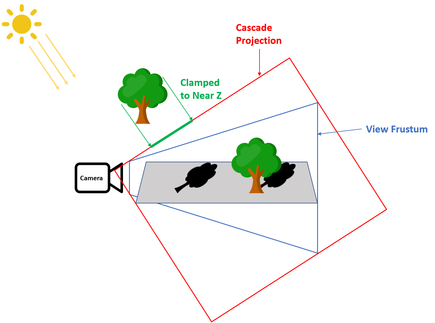
In this case we have a simple ground plane that’s visible to the main camera, and two trees that act as shadow casters. The rightmost tree is straightforward: it is within the main view frustum (in blue), and so it also sits comfortably within the single cascade projection for the directional light shadow map (in red). However the leftmost tree has the problem we mentioned previously: it is not visible to the main camera and is outside of the cascade projection, however it should still cast a visible shadow. With depth clipping disabled, that leftmost tree gets clamped to the cascade projection’s near clip plane, which is shown as the thick green line below the tree. These depth values of 0 still end up being less than the shadow depth value of any surfaces within the view frustum, and therefore they still end up being shadowed correctly.
GPU-Driven Cascade Setup and Scene Submission
This is a topic that’s both fun, and really frustrating. It’s fun because you can really start to exploit the flexibility of DX11-class GPU’s, and begin to break free of the old “CPU spoon-feeds the GPU” model that we’ve been using for so long now. It’s also frustrating because the API’s still hold us back a quite a bit in terms of letting the GPU generate its own commands. Either way it’s something I see people talk about but not a lot of people actually doing it, so I thought I’d give it a try for this sample. There’s actually 2 reasons to try something like this. The first is that if you can offload enough work to the GPU, you can avoid the heavy CPU overhead of frustum culling and drawing and/or batching lots and lots of meshes. The second is that it lets you do SDSM-style cascade optimization based on the depth buffer without having to read back values from the GPU to the CPU, which is always a painful way of doing things.
The obvious path to implementing GPU scene submission would be to make use of DrawInstancedIndirect/DrawIndexedInstancedIndirect. These API’s are fairly simple to use: you simply write the parameters to a buffer (with the parameters being the same ones that you would normally pass on the CPU for the non-indirect version), and then on the CPU you specify that buffer when calling the appropriate function. Since instance count is one of the parameters, you can implement culling on the GPU my setting the instance count to 0 when a mesh shouldn’t be rendered. However it turns out that this isn’t really useful, since you still need to go through the overhead of submitting draw calls and setting associated state on the CPU. In fact the situation is worse than doing it all on the CPU, since you have to submit each draw call even if it will be frustum culled.
Instead of using indirect draws, I decided to make a simple GPU-based batching system. Shadow map rendering is inherently more batchable than normal rendering, since you typically don’t need to worry about having specialized shaders or binding lots of textures when you’re only rendering depth. In my sample I take advantage of this by using a compute shader to generate one great big index buffer based on the results of a frustum culling pass, which can then be rendered in a single draw call. It’s really very simple: during initialization I generate a buffer containing all vertex positions, a buffer containing all indices (offset to reflect the vertex position in the combined position buffer), and a structured buffer containing the parameters for every draw call (index start, num indices, and a bounding sphere). When it’s time to batch, I run a compute shader with one thread per draw call that culls the bounding sphere against the view frustum. If it passes, the thread then “allocates” some space in the output index buffer by performing an atomic add on a value in a RWByteAddressBuffer containing the total number of culled indices that will be present in output index buffer (note that on my 7950 you should be able to just do the atomic in GDS like you would for an append buffer, but unfortunately in HLSL you can only increment by 1 using IncrementCounter()). I also append the draw call data to an append buffer for use in the next pass:
const uint drawIdx = TGSize * GroupID.x + ThreadIndex;
if(drawIdx >= NumDrawCalls)
    return;

DrawCall drawCall = DrawCalls[drawIdx];
if(FrustumCull(drawCall))
{
    CulledDraw culledDraw;
    culledDraw.SrcIndexStart = drawCall.StartIndex;
    culledDraw.NumIndices = drawCall.NumIndices;
    DrawArgsBuffer.InterlockedAdd(0, drawCall.NumIndices,
                                  culledDraw.DstIndexStart);

    CulledDrawsOutput.Append(culledDraw);
}
Once that’s completed, I then launch another compute shader that uses 1 thread group per draw call to copy all of the indices from the source index buffer to the final output index buffer that will be used for rendering. This shader is also very simple: it simply looks up the draw call info from the append buffer that tells it which indices to copy and where they should be copied, and then loops enough times for all indices to be copied in parallel by the different threads inside the thread group. The final result is an index buffer containing all of the culled draw calls, ready to be drawn in a single draw call:
const uint drawIdx = GroupID.x;
CulledDraw drawCall = CulledDraws[drawIdx];
for(uint currIdx = ThreadIndex; currIdx < drawCall.NumIndices; currIdx += TGSize)
{
    const uint srcIdx = currIdx + drawCall.SrcIndexStart;
    const uint dstIdx = currIdx + drawCall.DstIndexStart;

    CulledIndices[dstIdx] = Indices[srcIdx];

}
In order to avoid the min/max depth readback, I also had to port my cascade setup code to a compute shader so that the entire process could remain on the GPU. I was surprised to find that this was actually quite a bit more difficult than writing the batching system. Porting arbitrary C++ code to HLSL can be somewhat tedious, due to the various limitations of the language. I also ran into a rather ugly bug in the HLSL compiler where it kept trying to keep matrices in column-major order no matter what code I wrote and what declarations I used, which I suppose it tries to do as an optimization. However this really messed me up when I tried to write the matrix into a structured buffer, and expected it to be row-major. My advice for the future: if you need to write a matrix from a compute shader, just use a StructuredBuffer<float4> and write out the rows manually. Ultimately after much hair-pulling I got it to work, and finally achieved my goal of 0-latency depth reduction with no CPU readback!
In terms of performance, the GPU-driven path comes in about 0.8ms slower than the CPU version when the CPU uses 1 frame of latency for reading back the min/max depth results. I’m not entirely sure why it’s that much slower, although I haven’t spend much time trying to profile the batching shaders or the cascade setup shader. I also wouldn’t be surprised if the actual mesh rendering ends up being a bit slower, since I use 32-bit indices when batching on the GPU as opposed to 16-bit when submitting with the CPU. However when using the 0 frames of latency for the CPU readback, the GPU version turns it around and comes in a full millsecond faster on my PC. Obviously it makes sense that any additional GPU overhead would make up for the stall that occurs on the CPU and GPU when having to immediately read back data. One thing that I’ll point out is that the GPU version is quite a bit slower than the CPU version when VSM’s are used and pre-filtering is enabled. This is because the CPU path chooses an optimized blur shader based on the filter width for a cascade, and early outs of the blur process if no filtering is required. For the GPU path I got lazy and just used one blur shader that uses a dynamic loop, and it always runs the blur passes even if no filtering is requested. There’s no technical reason why you couldn’t do it the same way as the CPU path with enough motivation and DrawIndirects.
Comments:
With regard to SDSM, I have so many questions! With a great big vertex buffer, how would you manage skinning and world space transformations? I’m guessing you would need to generate one great big matrix buffer and eat the cost of having blend weights and indices on everything. Dealing with alpha test seems pretty daunting, maybe impossible? Also, handling objects getting added and removed as you would see in a normal game seems like it would be a headache.
#### [An Idiot]( "superidiot@idiots.com") -
I know I’m an idiot but there is something very simple I cannot understand about SDSM: Before writing to the view depth buffer, usually one cleans it to a max value (ie 1) so samples lower than that will be rendered. When doing the min/max reduction… how the max z is found? Shouldn’t it return always 1 if a sample is left uncovered/ showing the background leaving a 1 in the depth buffer? Sorry for my stupidity and thanks
#### [An Idiot]( "idiot@idiotmail.com") -
Thanks a lot Rocko! Now I have SDEVSM working in my game :)
#### [An Idiot]( "idiot@ranersintarsioent.com") -
Thanks! I was thinking of something like that. But what confused me is that I didn’t saw that in the PS code so I thought that maybe there was a way to do it without a branch. Now, giving it a better look, I can’t see also the four fetches one should do. I can only assume that “float4 depthSamples = DepthMap.GatherRed(LinearClampSampler, TexCoord);” someway does the four fetches and it also ignores values == 1.0? HLSL is quite a mystery for a GLSL user. Thanks for your quick reply.
#### [A sampling of shadow techniques | Light is beautiful](http://lousodrome.net/blog/light/2013/09/15/a-sampling-of-shadow-techniques/ "") -
[…] On his blog, Matt Pettineo writes about his experiments on cascaded shadow maps, including cascade optimization, shadow map filtering and GPU scene submission: A Sampling of Shadow Techniques. […]
#### [Alundra]( "segura.mikael@orange.fr") -
Hi MJP, SDSM begin to be an old technique, but it’s the lastest technique found for shadow (2011). Is SDSM too heavy to use or THIS IS the technique to use nowadays ?
#### [Alundra]( "segura.mikael@orange.fr") -
Another thing is : Why ReadBack is faster ?! I don’t get it. I have 5 FPS more on your sample disabling GPU submission, normally FPS is lower using a read-back, why this 5 FPS wasted ?!
#### [dishwasher](http://none "dishwasherblood@gmail.com") -
Now it works fine! Thank you very much for such a quick help!
#### [Development resources](http://www.sgc2000.co.uk/2014/03/development-resources/ "") -
[…] A sampling of shadow techniques […]
#### [dishwasher](http://none "dishwasherblood@gmail.com") -
Actually it seems something is wrong with it, here’s an example: LightColor.Initialize(tweakBar, “LightColor”, “SceneControls”, “Light Color”, “The color of the light”, Float3(10, 8, 5), true, 0.0f, 20.0f, 0,1.0f); Look at the last parameter - 0,1.0f. All the errors ale like that: MinCascadeDistance.Initialize(tweakBar, “MinCascadeDistance”, “Shadows”, “Min Cascade Distance”, “The closest depth that is covered by the shadow cascades”, 0.0f, 0.0f, 0,1.0f, 0,001.0f); 0,1.0f, 0,001.0f? It looks like something’s wrong with generating floats from attrubute strings?
#### [MJP](http://mynameismjp.wordpress.com/ "mpettineo@gmail.com") -
Okay, I think I figured out the problem. I didn’t specify the culture when outputting strings for float parameters, and it looks like it was using commas instead of decimal points for your locale. Clearly I am not an experienced C# programmer! I uploaded a new zip with some fixes, so could you download that and give it a try?
#### [Sample Framework Updates | The Danger Zone](http://mynameismjp.wordpress.com/2013/09/16/sample-framework-updates/ "") -
[…] may have noticed that my latest sample now has a proper UI instead of the homegrown sliders and keyboard toggles that I was using in my […]
#### [MJP](http://mynameismjp.wordpress.com/ "mpettineo@gmail.com") -
Thank you for the links Christoph! I actually wasn’t familiar with that Nvidia extension, and I hadn’t seen your presentation either. Sounds very useful indeed!
#### [MJP](http://mynameismjp.wordpress.com/ "mpettineo@gmail.com") -
Hi Jamie! What I did in the demo is definitely not production-ready, and I’m not sure if I would even do it exactly the same way if I were going to try to ship with it. For this sample I handled the character by repeating the entire batching process for its meshes, and if you were to do it that way you could handle skinning as long as you also had the bone weight/indices in a combined vertex buffer as well. Or if you could set up system for pre-skinning vertices and writing them out (either via stream-out, or better yet by directly writing to the buffer from the vertex shader) then it would definitely make things easier. In fact if you did that, you could probably stream out vertices from multiple skinned meshes into a the same batch, and then run the culling/batching process on lots of skinned objects simultaneously. Alpha-test would definitely be pretty tricky, although you could always fall back to a DrawIndirect-based approach for anything that’s difficult to batch.
#### [dishwasher](http://none "dishwasherblood@gmail.com") -
Sample doesn’t build in VS2013: 1> AppSettings.cpp 1>AppSettings.cpp(129): error C2660: ‘SampleFramework11::ColorSetting::Initialize’ : function does not take 11 arguments 1>AppSettings.cpp(147): error C2660: ‘SampleFramework11::FloatSetting::Initialize’ : function does not take 10 arguments 1>AppSettings.cpp(174): error C2660: ‘SampleFramework11::FloatSetting::Initialize’ : function does not take 11 arguments 1>AppSettings.cpp(177): error C2660: ‘SampleFramework11::FloatSetting::Initialize’ : function does not take 10 arguments 1>AppSettings.cpp(183): error C2660: ‘SampleFramework11::FloatSetting::Initialize’ : function does not take 11 arguments 1>AppSettings.cpp(186): error C2660: ‘SampleFramework11::FloatSetting::Initialize’ : function does not take 11 arguments 1>AppSettings.cpp(189): error C2660: ‘SampleFramework11::FloatSetting::Initialize’ : function does not take 11 arguments 1>AppSettings.cpp(192): error C2660: ‘SampleFramework11::FloatSetting::Initialize’ : function does not take 10 arguments 1>AppSettings.cpp(195): error C2660: ‘SampleFramework11::FloatSetting::Initialize’ : function does not take 10 arguments 1>AppSettings.cpp(201): error C2660: ‘SampleFramework11::FloatSetting::Initialize’ : function does not take 12 arguments 1>AppSettings.cpp(204): error C2660: ‘SampleFramework11::FloatSetting::Initialize’ : function does not take 10 arguments 1>AppSettings.cpp(219): error C2660: ‘SampleFramework11::FloatSetting::Initialize’ : function does not take 10 arguments 1>AppSettings.cpp(222): error C2660: ‘SampleFramework11::FloatSetting::Initialize’ : function does not take 10 arguments 1>AppSettings.cpp(225): error C2660: ‘SampleFramework11::FloatSetting::Initialize’ : function does not take 10 arguments 1>AppSettings.cpp(228): error C2660: ‘SampleFramework11::FloatSetting::Initialize’ : function does not take 10 arguments 1>AppSettings.cpp(231): error C2660: ‘SampleFramework11::FloatSetting::Initialize’ : function does not take 10 arguments 1>AppSettings.cpp(234): error C2660: ‘SampleFramework11::FloatSetting::Initialize’ : function does not take 13 arguments 1>AppSettings.cpp(237): error C2660: ‘SampleFramework11::FloatSetting::Initialize’ : function does not take 12 arguments 1>AppSettings.cpp(240): error C2660: ‘SampleFramework11::FloatSetting::Initialize’ : function does not take 11 arguments SettingsCompiler and SettingsCompilerAttributes compiled successfully.
#### [MJP](http://mynameismjp.wordpress.com/ "mpettineo@gmail.com") -
I just installed VS 2013 on my PC, and the sample builds fine for me. I tried both upgrading the project and not upgrading it, and it compiles either way. Does the code generated in AppSettings.cpp look okay?
#### [MJP](http://mynameismjp.wordpress.com/ "mpettineo@gmail.com") -
Hi Sam, We’ve been using EVSM and SDSM with similar cascade techniques for some time now in our game, although we have a lot of little tweaks, fixes, and platform-specific optimizations to make everything work in a production setting. We’re not currently doing any GPU-driven submission, but I have plans to implement something specific to PS4 that’s even more optimal than what I did in this sample. -Matt
#### [Christoph Kubisch](http://gravatar.com/crazybutcher "crazybutcher@luxinia.de") -
Hi thanks for the article! For the GPU-driven submission OpenGL provides multi-draw-indirect which allows for quite efficent read-back less culling. Been doing research on this topic at NVIDIA, some results were shown at thise years GTC http://on-demand.gputechconf.com/gtc/2013/presentations/S3032-Advanced-Scenegraph-Rendering-Pipeline.pdf from slide 35 on.There is http://www.opengl.org/registry/specs/NV/bindless_multi_draw_indirect.txt which allows to source from arbitrary buffer locations, as well as http://www.opengl.org/registry/specs/ARB/indirect_parameters.txt which means you can batch the jobs efficiently.
#### [Rim]( "remigius@netforge.nl") -
Thanks for the treatise, Matt. Although it’s been quite a while since I touched DirectX, I still found it educational to read up on the advances in shadowing and if nothing else, the article got me amped to finally give those fancy compute shaders a try for non-graphics stuffs. Cheers!
#### [Sam Martin]( "sam@palgorithm.co.uk") -
Hi Matt, This is a great summary of the state of the art and the gpu-driven cascade rendering is really good to see. Are you guys intending on using this approach in production? Cheers, Sam
#### [Shadow Mapping Summary – Part 1](http://the-witness.net/news/2013/09/shadow-mapping-summary-part-1/ "") -
[…] not going to try to address that here, but just as I was writting this Matt Pettineo released a good overview of some of the different techniques available that is a good starting point. Instead, I’ll […]
#### [fenbf](http://www.bfilipek.com "joebaf@gmail.com") -
Impressive! I made similar app for my master thesis: I’ve used openGL and tested CSV vs standard shadow map techniques + some additional improvements.
#### [MJP](http://mynameismjp.wordpress.com/ "mpettineo@gmail.com") -
I just ignore any z samples that aren’t < 1.0. This keeps you from considering background/sky pixels when computing the max depth, as long as you force your skybox to render at the far clip plane.
#### [MJP](http://mynameismjp.wordpress.com/ "mpettineo@gmail.com") -
GatherRed just returns the the red component of the 4 samples that would be used for bilinear filtering, so basically it gives you a 2x2 grid of depth samples in this case. That file is probably a little confusing because there’s actually 4 shaders in there. The two that actually get used in the sample are DepthReductionInitialCS and DepthReductionCS, which are the compute shader versions. The “Initial” shader is the one that’s run first, and actually samples the depth buffer. When MSAA is enabled it loads all N subsamples for a given pixel, and when MSAA is not enabled it just grabs the 1 sample. In both cases it does a check of “if(depthSample < 1.0f)” to decide if it should use a given depth sample, which is on lines 149 and 161. Taking a look at the code, it looks like the pixel shader version doesn’t do the check if MSAA is disabled. This is definitely a bug, which is probably why were you confused. That code path never actually gets taken in the sample (I always had MSAA enabled), so I never noticed it. Sorry about that!
#### [Shadow Sample Update | The Danger Zone](https://mynameismjp.wordpress.com/2015/02/18/shadow-sample-update/ "") -
[…] the implementation of MSM is very straightforward, and so I decided to just integrate it into my old shadows sample. I updated the corresponding blog post and re-uploaded the binary + source, so if you’d like […]
#### [An Idiot]( "idiot@idiotmail.com") -
Just another comment to deepen my undestanding: When you compute the frustum slices, you take the linear Z min and maxes for the slice and then multiply them with the frustum rays between near and far corners to get the slice corners. However, the Z min and maxes work for for a ray at the center on the frustum and using them directly on the corner gives different planes, that for example, if using a pretty tight near to the geometry may leave parts out. What I did is to get the central ray of the frustum normalized and then use it to project the depths to the corners. ie: nearCornerRay = cornerRay * dot(normalize(cornerRay),centralRay*prevSplitDist); farCornerRay = cornerRay * dot(normalize(cornerRay),centralRay*splitDist); That fixed my problems, but I have no confidence in that I’m doing the correct thing. Thanks!
#### [OpenGL Cascaded Shadow Maps | Make Games, Not War](https://johanmedestrom.wordpress.com/2016/03/18/opengl-cascaded-shadow-maps/ "") -
[…] I’d make a simple project in OpenGL for anyone interested. It is based on this example: https://mynameismjp.wordpress.com/2013/09/10/shadow-maps/ which explains it in great detail. I’ll go through the relevant code and a download link […]
#### [MJP](http://mynameismjp.wordpress.com/ "mpettineo@gmail.com") -
Thanks! The code for the OptimizedPCF path was generously provided by Ignacio Castaño, who didn’t provide an implementation for a 9x9 filter. I had been meaning to write it myself, but never got around to it. :(
#### [Кирилл Грустнёв](https://plus.google.com/111128623163722713524 "simpetar@gmail.com") -
Hello, Matt. I do not know whom to ask, so i decided to ask you, as your articles are always very profound and you clarify details that no one clarifies :-) i’m implementing now sdsm technique from Andrew Lauritzen article with evsm filtering using opengl 4.5. So i read almost everything about esm, vsm, and other *sm, but cannot understand some points. I also looked through your shadow sample and intel’s also (i do not know direcx, really). So the questions: 1. When we used positive and negative exponent factors in evsm, why the first is 42 (this i understand), but the last is 5(this is completely obscured to me). 2. All the articles about shadow mapping say that you should use front face culling when rendering to the shadow map (this should decrease wrong selfshadowing and acne), but both you and andrew lauritzen use NoCull in your samples. Why? 3. In Andrew’s sample he “normalizes” exponent factors with cascade ranges, to make the transition between cascades less noticeable. You do not do that. I have ranges from several meters to 10s of kilometers (flight simulator). Is there any point to do that? 4. When blurring evsm, does it make sense to blur with decreasing kernel size (for example, 7x blur for cascade 0, 5x for 1, 3x for 2 and no blur for the last. Is there any “state of the art” technique? 5. The same question with light space orientation relative to camera space. I have only sun direction (z-axis), so i can rotate the light space basis around it (xy axes), is there the “right way” to do that? stick it to camera “up” vector or to world up vector? 6. Is there any point to do some shear transformation to light space. Could it help to better utilize sm resolution, I didn’t see any articles on. Now my lighspace is a box. 7. Everybody uses square shadow maps (1024x1024 for ex.). Is it possible to find better aspect knowing scene parameters. Thank you for your answer :-):-)
#### [Shadow Filtering For Pointlights | kosmonaut games](https://kosmonautblog.wordpress.com/2017/03/25/shadow-filtering-for-pointlights/ "") -
[…] Should you be looking for different shadow filtering algorithms, you have come to the wrong place – the right place would be here:https://mynameismjp.wordpress.com/2013/09/10/shadow-maps/ […]
#### []( "") -
Great work! I just curious: SampleShadowMapOptimizedPCF() in Mesh.hlsl does not contain branch for FilterSize_ == 9. Is it by design?
#### [Steve Smith]( "baboon_king@hotmail.com") -
This is awesome stuff. I’m curious (and this has been driving me nuts for hours now) - but how does your mesh rendering shader have depth/w always biased from 0 to 1? I’m trying to follow this in my own code (and even for example the DirectX cascaded shadow maps sample) and these values are *way* different. You’re doing some magic here I can’t figure out… help!
#### [MJP](http://mynameismjp.wordpress.com/ "mpettineo@gmail.com") -
Hey Steve! Exactly which depth value are you referring to here? Are you talking the depth of the pixel from the light’s point of view, that’s used to compare against the shadow map value? In general the range of the result of when calculating z / w is a property of the projection matrix that you’re using. In my sample the sun shadows are rasterized using an orthographic projection, where z is calculated as (viewSpaceZ - NearClip) / (FarClip - NearClip), and w is always just 1.0. So it naturally ends up in the [0, 1] range, since any other values would get clipped by the near/far clip planes. Does that answer your question? Feel free to let me know if I’m misunderstanding.
#### [Steve Smith]( "baboon_king@hotmail.com") -
I did not explain that clearly, apologies. The shadow gen stuff makes sense (and I think I have that all figured out). On the rendering side, you have a super-simple vertex shader that spits out a value (DepthVS) from PositionCS.w. Side by side, my view projection and yours are almost identical, but my w value range appears to be in the order of my near/far clip range (so around 300). The only difference I see is that I’m using non-transposed clipspace matrix (which works if you reverse the float4/matrix parameters in the transform mul) but I tried flipping that around and didn’t see a difference.
#### [Steve Smith]( "baboon_king@hotmail.com") -
Oh dear lord. I was debugging visually, and completely forgot you had full HDR with tone-mapping (I had mine turned off). Hoo boy. Somebody needs more sleep.
#### [MJP](http://mynameismjp.wordpress.com/ "mpettineo@gmail.com") -
Ahh okay, that makes more sense! So yeah: the w component in that case is equivalent to the z component of the view-space vertex position. A perspective projection matrix will typically be setup with the fourth column equal to [0, 0, 1, 0], which ends up setting w = x * 0 + y * 0 + z * 1 + 1 * 0. So you would expect that to be somewhere in the range of [NearClip, FarClip], which is what you’re seeing.
#### [Steve Smith]( "baboon_king@hotmail.com") -
Thanks. And thanks for the sample too, it’s been incredibly useful. I’ve not seen samples this well thought out and well executed since I had access to the old Microsoft ATG stuff. So - thank you.