Bindless Texturing for Deferred Rendering and Decals
https://github.com/TheRealMJP/DeferredTexturing
https://github.com/TheRealMJP/DeferredTexturing/releases (Precompiled Binaries)
To Bind, or Not To Bind
Unless you’ve been in a coma for the past year, you’ve probably noticed that there’s a lot of buzz and excitement around the new graphics API’s that are available for PC and mobile. One of the biggest changes brought by both D3D12 and Vulkan is that they’ve ditched the old slot-based system for binding resources that’s been in use since…forever. In place of the old system, both API’s have a adopted a new model[1] based around placing opaque resource descriptors in contiguous ranges of GPU-accessible memory. The new model has the potential to be more efficient, since a lot of hardware (most notably AMD’s GCN-based GPU’s) can read their descriptors straight from memory instead of having to keep them in physical registers. So instead of having the driver take a slot-based model and do behind-the-scenes gymnastics to put the appropriate descriptors into tables that the shader can use, the app can just put the descriptors in a layout that works right from the start.
The new style of providing resources to the GPU is often referred to as “bindless”, since you’re no longer restricted to explicitly binding textures or buffers through dedicated API functions. The term “bindless” originally comes from Nvidia, who were the first to introduce the concept[2] through their NV_bindless_texture[3] extension for OpenGL. Their material shows some serious reductions in CPU overhead by skipping standard resource binding, and instead letting the app place 64-bit descriptor handles (most likely they’re actually pointers to descriptors) inside of uniform buffers. One major difference between Nvidia bindless and D3D12/Vulkan bindless is that the new APIs don’t allow you to simply put descriptor handles inside of constant/uniform buffers. Instead, they require you to manually specify (through a root signature) how you’ll organize your tables of descriptors for a shader. It might seem more complicated the Nvidia extension, but doing it this way has a big advantage: it lets D3D12 still support hardware that has no support (or limited support) for pulling descriptors from memory. It also still allows you to go full-on Nvidia-style bindless via support for unbounded texture arrays in HLSL. With unbounded arrays you can potentially put all of your descriptors in one giant table, and then index into that array using values from root constants/constant buffers/structured buffers/etc. This basically lets you treat an integer the same as a “handle” in Nvidia’s approach, with the added benefit that you don’t need to actually store a full 64-bit integer. Not only can this be really efficient, but it also opens the door to new rendering techniques that use GPU-generated values to determine which textures to fetch from.
Deferred Texturing
One such use case for bindless textures is deferred texturing. The concept is pretty straightforward: instead of writing out a G-Buffer containing all of the material parameters required for shading, you instead write out your interpolated UV’s as well as a material ID. Then during your deferred pass you can use your material ID to figure out which textures you need to sample, and use the UV’s from your G-Buffer to actually sample them. The main benefit is that you can ensure that your textures are only sampled for visible pixels, without worrying about overdraw or quad packing. Depending on your approach, you may also be able to save on some G-Buffer space by virtue of not having to cram every material parameter in there. In practice you actually need more than just UV and material ID. For normal mapping you need your full tangent frame, which at minimum requires a quaternion. For mipmaps and anisotropic filtering we also need the screen-space derivatives of our UV’s. These can computed in the pixel shader and then explicitly stored in the G-Buffer, or you can compute them from G-Buffer as long as you’re willing to live with occasional artifacts. Nathan Reed has a nice write-up[4] on his blog discussing the various possibilities for G-Buffer layouts, so I would suggest reading through his article for some more details.
The place where bindless helps is in the actual sampling of the material textures during the deferred lighting phase. By putting all of your texture descriptors into one big array, the lighting pass can index into that array in order to sample the textures for any given material. All you need is a simple mapping of material ID -> texture indices, which you can do by indexing into a structured buffer. Of course it’s not really required to have bindless in order to pull this off. If you’re willing to stuff all of your textures into a big texture array, then you could achieve the same thing on D3D10-level hardware. Or if you use virtual mapping, then it’s pretty trivial to implement since everything’s already coming from big texture atlases. In fact, the virtual mapping approach has already been used in a shipping game, and was described at SIGGRAPH last year[5][6]. That said, the bindless approach is probably the easiest to get running and also places the least constraints on existing pipelines and assets.
Go Go Gadget D3D12!
As a way to test out the brand-new D3D12 version of my sample framework, I decided to have a go at writing a simple implementation of a deferred texturing renderer. It seemed like a good way to get familiar with some of the new features offered by D3D12, while also making sure that the new version of my sample framework was ready for prime-time. I also hoped that I could gain a better understanding of some of the practical issues involved in implementing deferred texturing, and use the experience to judge whether or not it might be a appealing choice for future projects.
Here’s a quick breakdown of how I ultimately set up my renderer:
- Bin lights and decals into clusters
- 16x16 tiles aligned to screen space, 16 linearly-partitioned depth tiles
- Render sun and spotlight shadows
- 4 2048x2048 cascaded shadow maps for the sun
- 1024x1024 standard shadow maps for each spotlight
- Render scene to the G-Buffer
- Depth (32bpp)
- Tangent frame as a packed quaternion[7] (32bpp)
- Texture coordinates (32bpp)
- Depth gradients (32bpp)
- (Optional) UV gradients (64bpp)
- Material ID (8bpp)
- 7-bit Material index
- 1-bit for tangent frame handedness
- If MSAA is not enabled:
- Run a deferred compute shader that perfoms deferred shading for all pixels
- Read attributes from G-Buffer
- Use material ID to get texture indices, and use those indices to index into descriptor tables
- Blend decals into material properties
- Render the sky to the output texture, using the depth buffer for occlusion
- Run a deferred compute shader that perfoms deferred shading for all pixels
- Otherwise if MSAA is enabled
- Detect “edge” pixels requiring per-sample shading using Material ID
- Classify 8x8 tiles as having either having edges or having no edges
- Render the sky to an MSAA render target texture, using the depth buffer for occlusion
- Run a deferred compute shader for non-edge tiles, shading only 1 subsample per pixel
- Run a deferred compute shader for edge tiles, shading 1 subsample for non-edge pixels and all subsamples for edge pixels
- Resolve MSAA subsamples to a non-MSAA texture
- Post-processing
- Present
In order to have another reference point for evaluating quality and performance, I also decided to implement a clustered forward[8] path side-by-side with the deferred renderer:
- Bin lights into clusters (16x16 tiles aligned to screen space, 16 linearly-partitioned depth tiles)
- Render sun and spotlight shadows
- (optional) Render scene depth prepass
- Render scene with full shading
- Read from material textures
- Blend decals into material properties
- Apply sunlight and spotlights
- if MSAA is enabled
- Resolve MSAA subsamples to a non-MSAA texture
- Post-processing
- Present
Light Clustering/Binning
As you may have already noticed, I used the same clustered approach to binning lights for both the deferred and forward paths. I did this because it was simpler than having two different approaches to light selection, and it also seemed more fair to take that aspect out of the equation when comparing performance. However you could obviously use whatever approach you’d like for binning lights when using deferred texturing, such as classic light bounds rasterization/blending or tile-based subfrustum culling[9].
To implement the actual binning, I used a similar setup to what was described in Emil Persson’s excellent presentation[8] from SIGGRAPH 2013. If you’re not familiar, the basic idea is that you chop up your view frustum into a bunch subfrusta, both in screen-space XY as well as along the Z axis. This essentially looks like a voxel grid, except warped to fit inside the frustum shape of a perspective projection. This is actually rather similar to the approach used in tiled deferred or Forward+[10] rendering, except that you also bucket along Z instead of fitting each subfrustum to the depth buffer. This can be really nice for forward rendering, since it lets you avoid over-including lights for tiles with a large depth range.
In the Avalanche engine they decided to perform their light binning on the CPU, which is feasible since the binning doesn’t rely on a depth buffer. Binning on the CPU can make a lot of sense, since a typical GPU approach to culling will often have many redundant calculations across threads and thread groups.It’s also possible make it pretty fast through CPU parallelization, as demonstrated by Intel’s Clustered Forward Shading sample[11].
For my own implementation I decided that I wanted to stick with the GPU, and so I went with a different approach. Having shipped a game that used a Forward+-style renderer, I’m pretty disappointed with the results of using a typical subfrustum plane-based culling scheme in a compute shader. The dirty secret[12] of using plane/volume tests for frustum culling is that they’re actually quite prone to false positives. The “standard” test can only exclude when your bounding volume is completely on the wrong side of one or more of your frustum planes. Unfortunately this means that it will fail for cases where the bounding volume intersects multiple planes at points outside the frustum. Even more unfortunate is that this particular case becomes more likely as your bounding volumes become large relative to your frustum, which is typically the case for testing lights against subfrusta. Spotlights are especially bad in this regard, since the wide portion will often intersect the planes of subfrusta that are actually just outside the narrower tip:
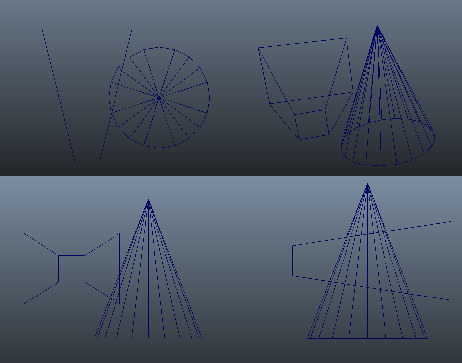
The top-right image shows a 3D perspective view, where you can clearly see that the cone in this situation doesn’t actually intersect with the frustum. However if you look at the orthographic views, you can also see that the cone manages to be on both sides of the frustum’s right plane. In practice you end up getting results like the following (tiles colored in green are “intersecting” with the spotlight):
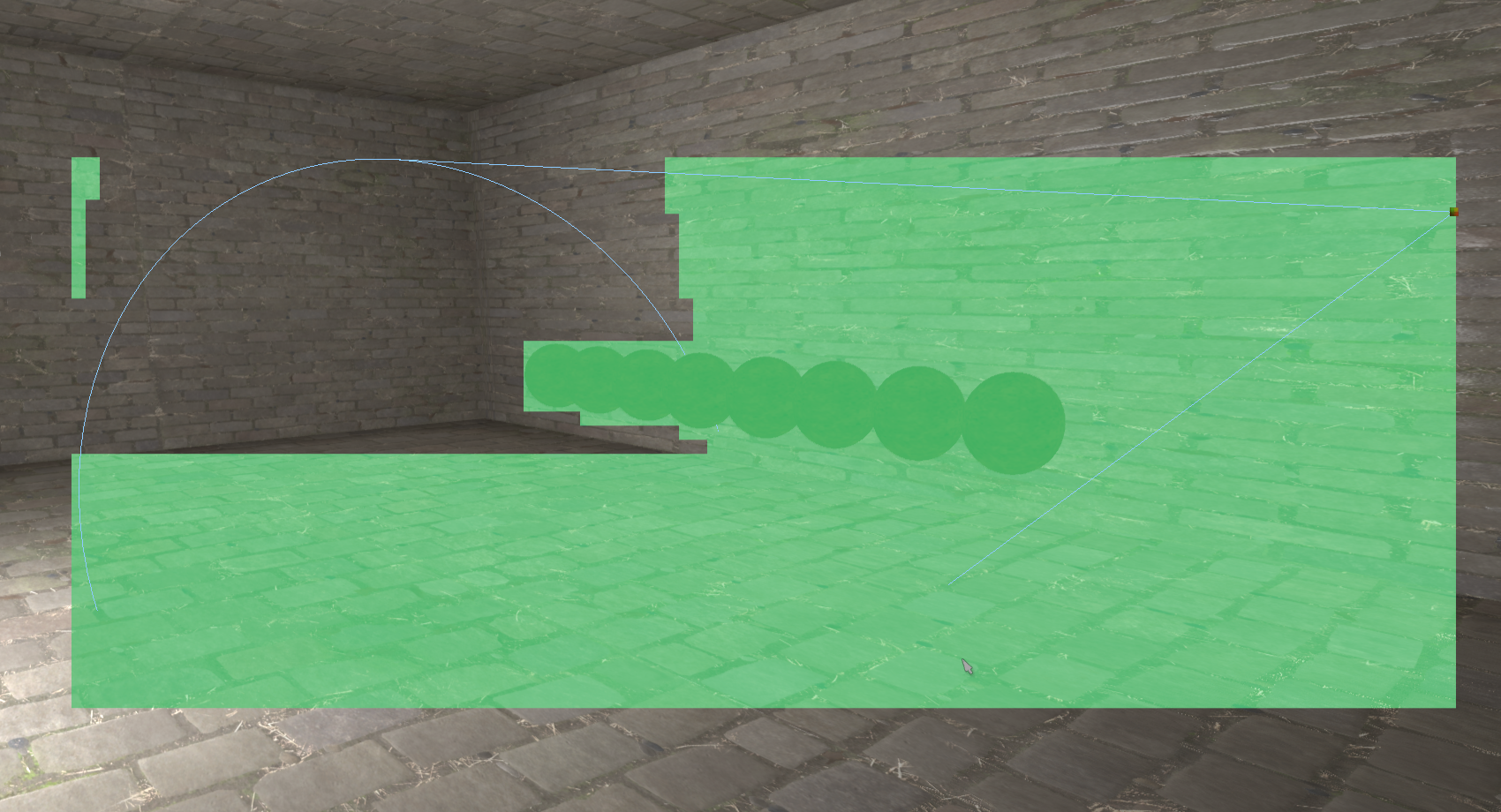
As you can see, you can end up with a ton of false positives. In fact towards the right we’re basically just filling in the screen-aligned AABB of the bounding cone, which turns into a whole lot of wasted work for those pixels.
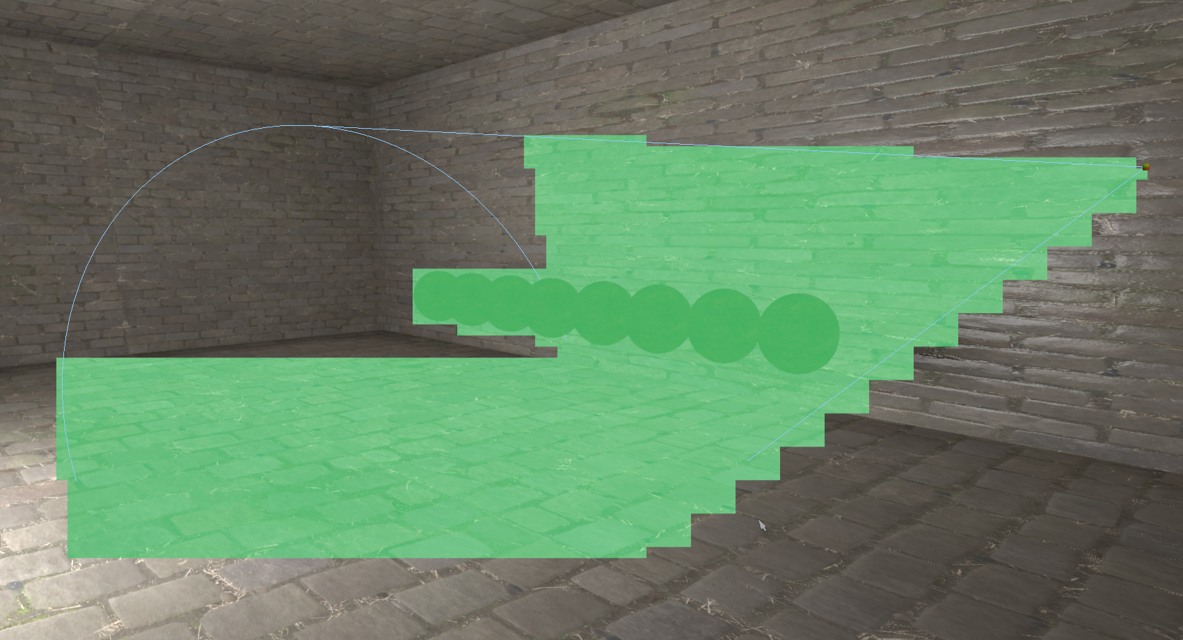
This drove me nuts on The Order, since our lighting artists liked to pack our levels full of large, shadow-casting spotlights. On the CPU side I would resort to expensive frustum-frustum tests for shadow-casting spotlights, which makes sense when you consider that you can save a lot of CPU and GPU time by culling out an entire shadow map. Unfortunately frustum/frustum wasn’t a realistic option for the tiled subfrustum culling that was performed on the GPU, and so for “important” lights I augmented the intersection test with a 2D mask generated via rasterization of the bounding cone. The results were quite a bit better:
For this demo, I decided to take what I had done on The Order and move it into 3D by binning into Z buckets as well. Binning in Z is a bit tricky, since you essentially want the equivalent of solid voxelization except in the projected space of your the frustum. Working in projected space rules out some of the common voxelization tricks, and so I ended up going with a simple 2-pass approach. The first pass renders the backfaces of a light’s bounding geometry, and marks the light’s bit (each cluster stores a bitfield of active lights) in the furthest Z bucket intersected by the current triangle within a given XY bucket. To conservatively estimate the furthest Z bucket, I use pixel shader derivatives to get the depth gradients, and then compute the maximum depth at the corner of the pixel. This generally works OK, but when the depth gradient is large it’s possible to extrapolate off the triangle. To minimize the damage in these cases, I compute a view-space AABB of the light on the CPU, and clamp the extrapolated depth to this AABB. After the backfacing pass, the frontfaces are then rendered. This time, the pixel shader computes the minimum depth bucket, and then walks forward along view ray until encountering the bucket that was marked by the backface pass. Here’s a visualization of the binning for a single light in my demo:
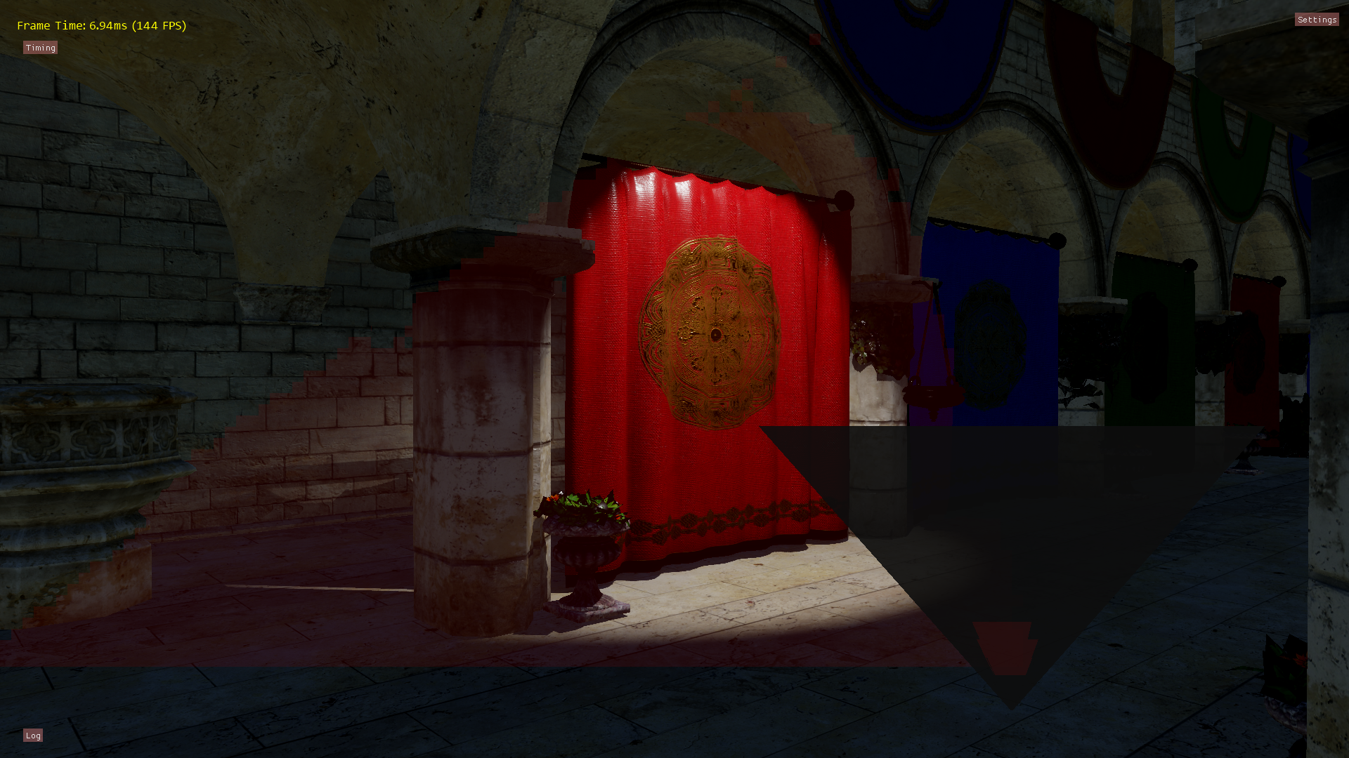
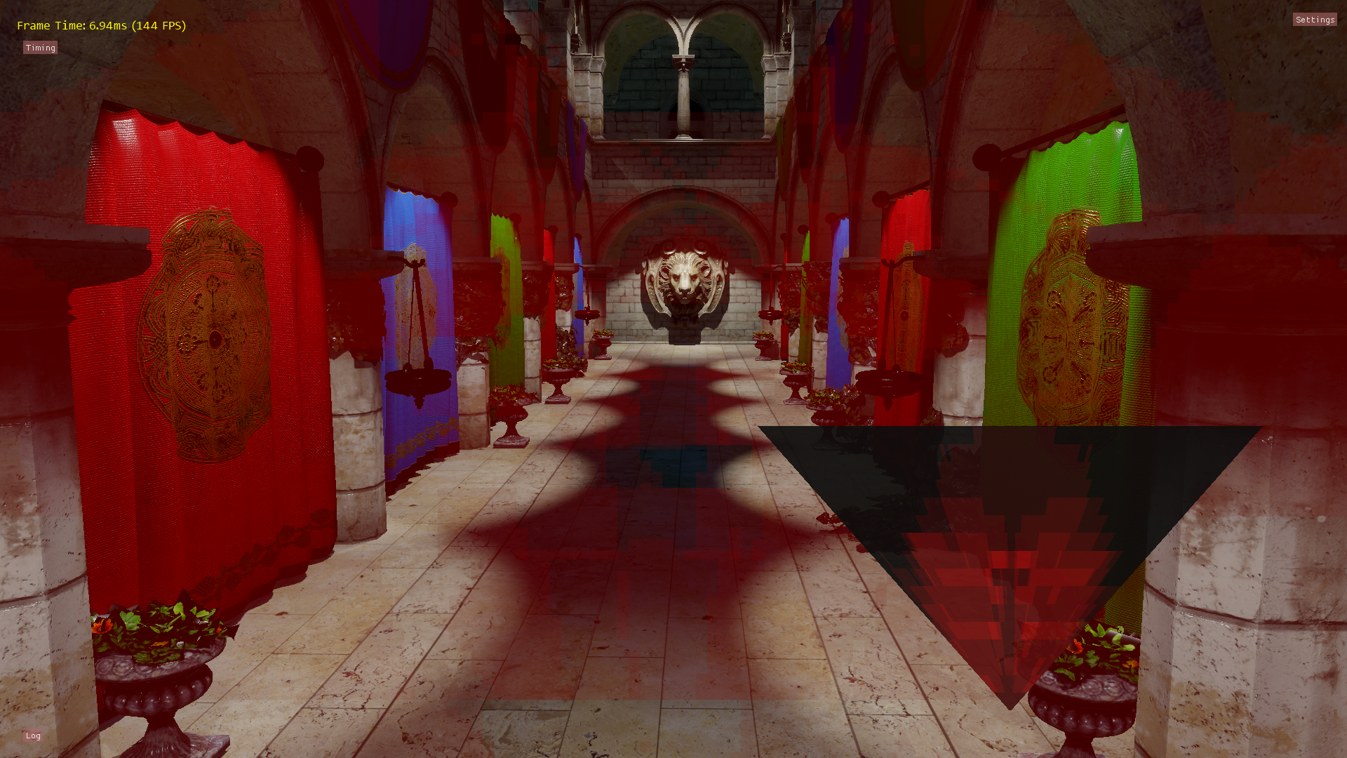
The pixels marked in red are the ones that belong to a cluster where the light is active. The triangle-shaped UI in the bottom right is a visualization that shows the active clusters for the XZ plane located at y=0. This helps you to see how well the clustering is working in Z, which is where the most errors occur in my implementation. Here’s another image showing the scene with all (20) lights enabled:
To do this robustly, you really want to use conservative rasterization[13]. I have this option in my demo, but unfortunately there are still no AMD GPU’s that support the feature. As a fallback, I also support forcing 4x or 8x MSAA modes to reduce the chance that the pixel shader won’t be executed for a covered tile. For The Order I used 8x MSAA, and it was never an issue in practice. It would really only be an issue if the light was very small on-screen, in which case you could probably just rasterize a bounding box instead. I should also point out that in my implementation the depth buffer is not used to accelerate the binning process, or to produce more optimally-distributed Z buckets. I implemented it this way so that there would not be additional performance differences when choosing whether or not to enable a Z prepass for the forward rendering path.
The G-Buffer

For rendering we’re going to need a G-Buffer in which we can store whatever information comes from our vertex data, as well as a material ID that we can use to look up the appropriate textures during the deferred pass. In terms of vertex information, we need both the tangent frame and the UV’s in order to sample textures and perform normal mapping. If we assume our tangent frame is an orthonormal basis, we can store it pretty compactly by using a quaternion. R16G16B16A16_SNORM is perfect for this use case, since it covers the expected range and provides great precision. However we can crunch it down[7] to 4 bytes per texel if we really want to keep it small (and we do!). The UV’s are stored in a 16-bit UNORM format, which gives us plenty of precision as long as we store frac(UV) to keep things between 0 and 1. In the same texture as the UV’s I also store screen-space depth gradients in the Z and W components. After that is an optional 64bpp texture for storing the screen-space UV gradients, which I’ll discuss in the next section. Finally, the G-Buffer also has an 8-bit texture for storing a material ID. The MSB of each textel is the handedness bit for the tangent frame, which is used to flip the direction of the bitangent once it’s reconstructed from a quaternion. This brings us to a total of 25 bytes per sample when storing UV gradients, and 17 when computing them instead.
UV and Position Gradients
One issue with deferred texturing is that you can’t rely on automatic mip selection via screen-space UV gradients when sampling the material textures. The gradients computed in a pixel shader will be wrong for quads that span multiple triangles, and in a compute shader they’re not available at all. The simplest way to solve this is to obtain the gradients in the pixel shader (using ddx/ddy) when rendering the scene to the G-Buffer, and then store those gradients in a texture. Unfortunately this means storing 4 separate values, which requires an additional 8 bytes of data per pixel when using 16-bit precision. It also doesn’t help you at all if you require positional gradients during your deferred pass, which can be useful for things like gobos, decals, filterable shadows, or receiver plane shadow bias factors. Storing the full gradients of world or view-space position would be silly, but fortunately we can store depth gradients and use those to reconstruct position gradients. Depth gradients only need 2 values instead of 6, and we can use a 16-bit fixed-point format instead of floating-point. They also have the nice property of being constant across the surface of a plane, which makes them useful for detecting triangle edges.
Both the UV and depth gradients can be computed in the deferred pass by sampling values from neighboring pixels, but in practice I’ve found it’s actually somewhat tricky to get right. You have to be careful not to “walk off the triangle”, otherwise you might end up reading UV’s from a totally unrelated mesh. Unless of course your triangle is so small that none of your neighbors came from the same triangle, in which case walking off might be your only option. You also have to take care around UV seams, including any you might have created yourself by using frac()!
In my implementation, I decided to always store depth gradients (where “depth” in this case is the post-projection z/w value stored in the depth buffer) while supporting an option to either store or compute UV gradients. Doing it this way allowed me to utilize the depth gradients when trying to find suitable neighbor pixels for computing UV gradients, and also ensured that I always had high-quality positional gradients. The material ID was also useful here: by checking that a neighboring pixel used the same material and was also had the same depth gradients, I could be relatively certain that the neighbor was either from the same triangle, or from a coplanar triangle. The shader code for this step can be found here, if you’re interested.
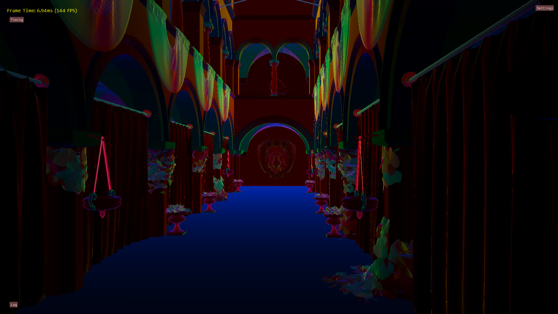
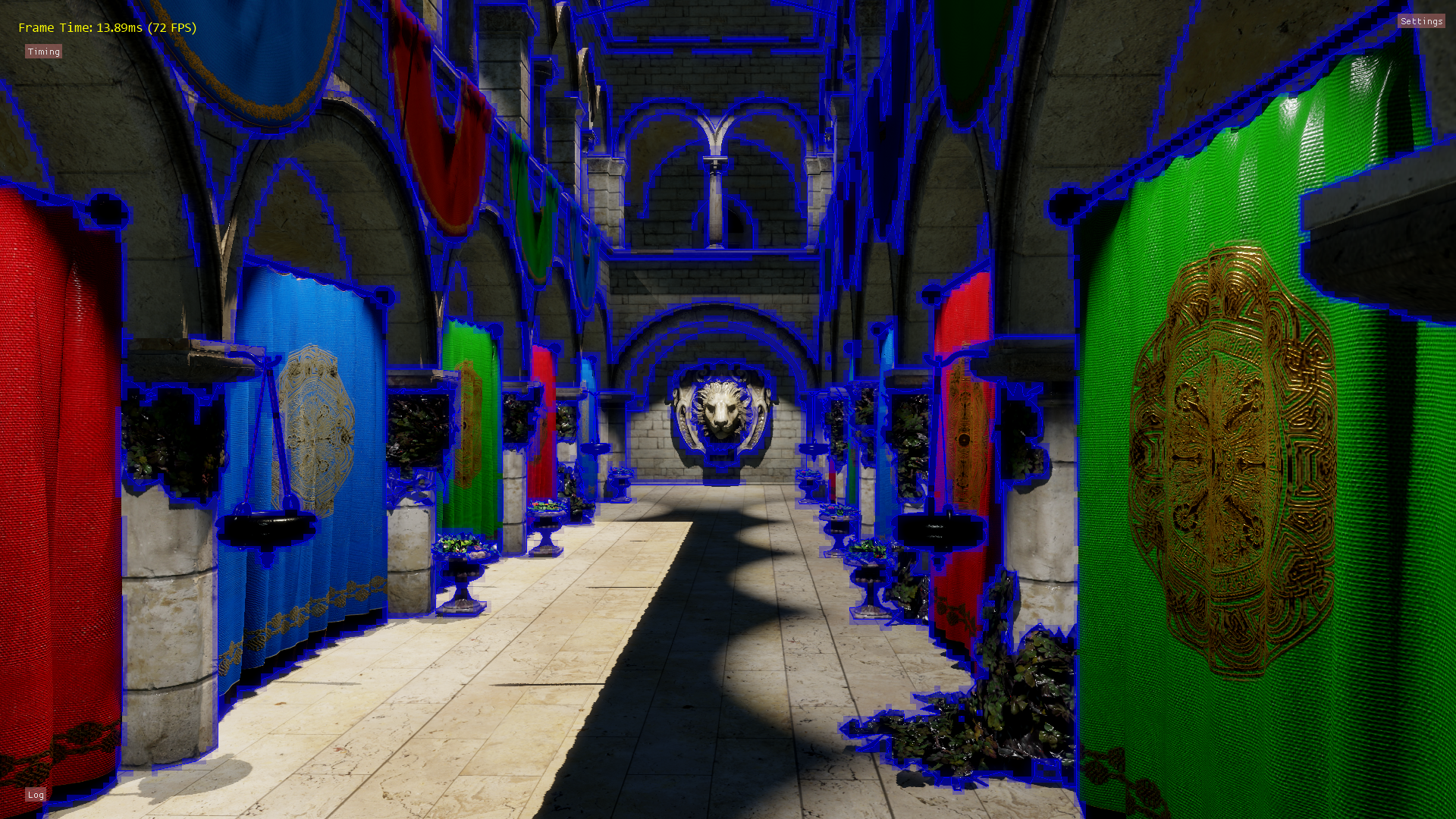
To assess the quality, let’s look at a visualization showing what the UV gradients look like when using ddx/ddy during forward rendering:
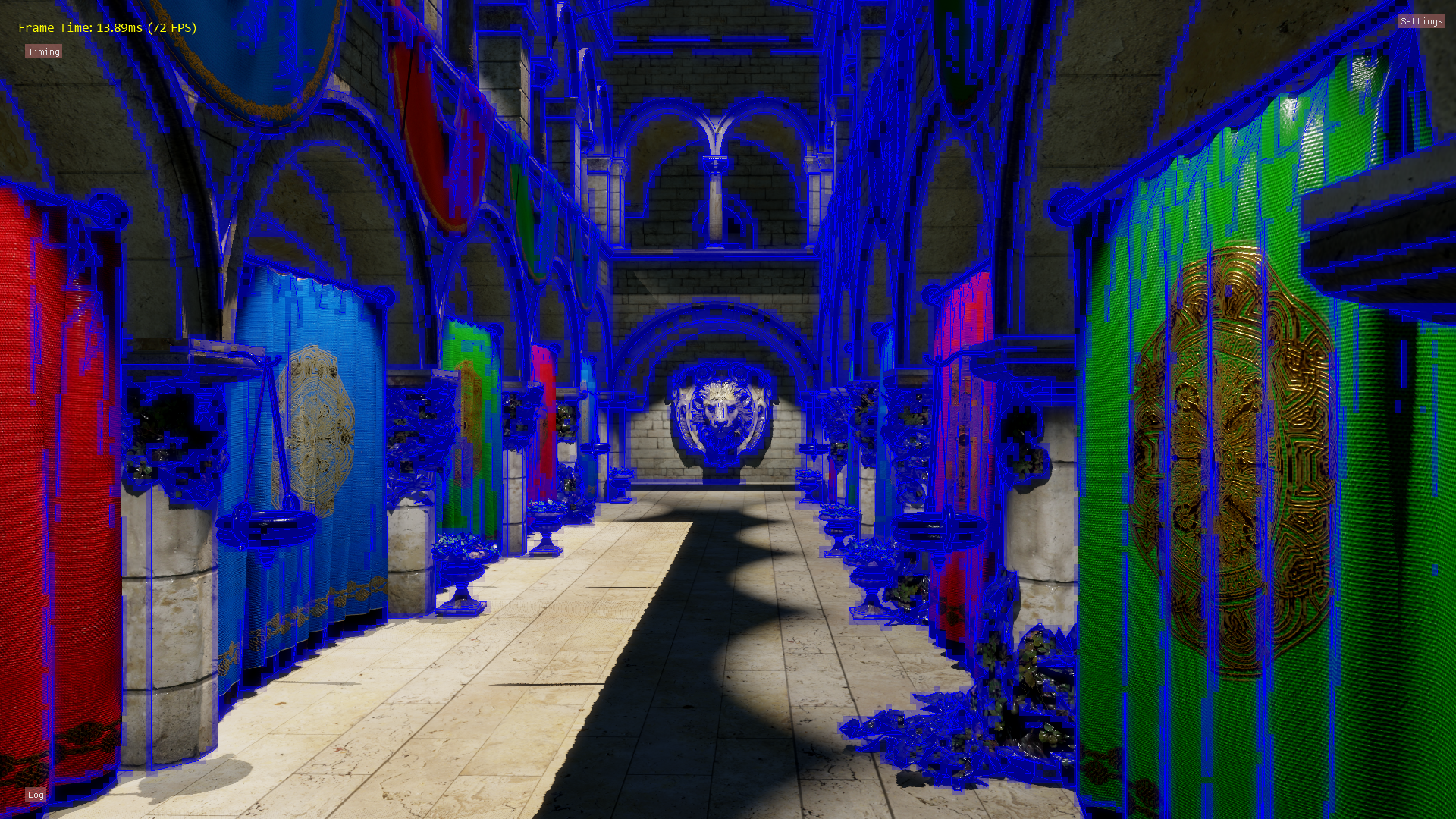
And here’s an image showing what computed UV gradients look like:
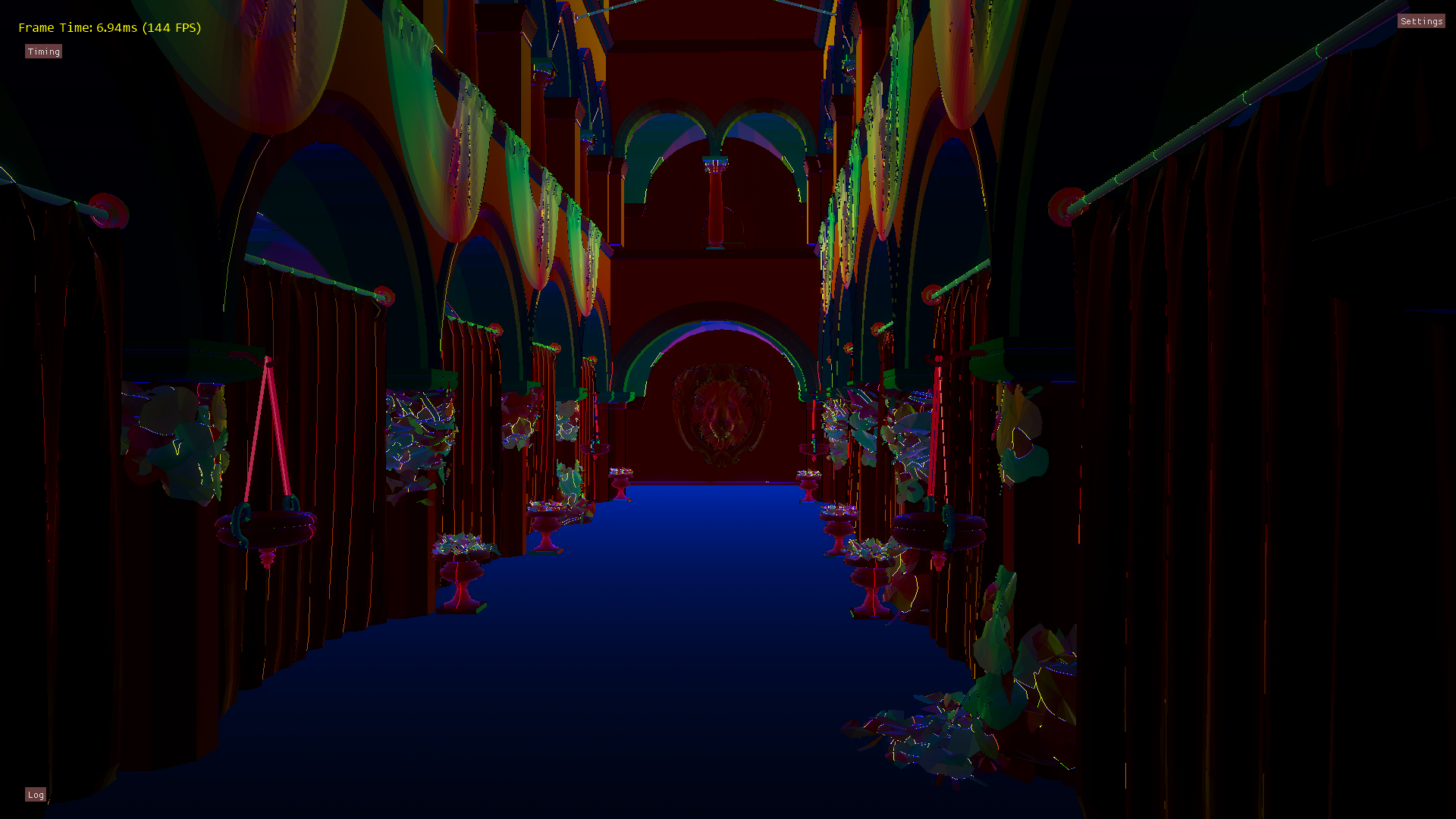
As you can see there’s quite a few places where my algorithm fails to detect neighbors (these pixels are dark), and other places where a neighboring pixel shouldn’t have been used at all (these pixels are bright). I’m sure the results could be improved with more time and cleverness, but you need to be careful that the amount of work done is enough to offset the cost of just writing out the gradients in the first place. On my GTX 970 it’s actually faster to store the gradients than it is to compute them when MSAA is disabled, but then it switches to the other way around once MSAA is turned on.
It’s worth noting that Sebastian’s presentation[5] mentions that they reconstruct UV gradients in their implementation (see page 45), although you can definitely see some artifacts around triangle edges in their comparison image. They also mention that they use “UV distance” to detect neighbors, which makes sense considering that they have unique UVs for their virtual texturing.
Non-MSAA Shading
For non-MSAA rendering, the deferred pass is pretty straightforward. First, the G-Buffer attributes are read from their textures and used to compute the original pixel position and gradients. UV gradients are then read from the G-Buffer if present, or otherwise computed from neighboring pixels. The material ID from the G-Buffer is then used to index into a structured buffer that contains one element per material, where each element contains the descriptor indices for the material textures (albedo, normal, roughness, and metallic). These indices are used to index into a large descriptor table containing descriptors for every texture in the scene, so that the appropriate textures can be sampled using the pixel’s UV coordinates and derivatives.
Once all of the surface and material parameters are read, they are passed into a function that performs the actual shading. This function will loop over all lights that were binned into the pixel’s XYZ cluster, and compute the reflectance for each light source. This requires evaluating the surface BRDF, and also applying a visibility term that comes from the light’s 1024x1024 shadow map. The shadow map is sampled with a 7x7 PCF kernel that’s implemented as an optimized, unrolled loop that makes use of GatherCmp instructions. This helps to make the actual workload somewhat representative of what you might have in actual game, instead of biasing things too much towards ALU work. My scene also has a directional light from the sun, which uses 4 2048x2048 cascaded shadow maps for visibility. Finally, an ambient term is applied by means of a set SH coefficients representing the radiance from the skydome.
MSAA Edge Detection and Tile Classification
Just like any other kind of deferred rendering, MSAA needs special care. In particular we need to determine which pixels contain multiple unique subsamples, so that we can shade each subsample individually during the deferred pass. The key issue here is scheduling: the “edge” pixels that require subsample shading will typically be rather sparse in screen space, which makes dynamic branching a poor fit. The “old-school” way of scheduling is to create a stencil mask from the edge pixels, and then render in two pixel shader passes: one pass for per-pixel shading, another for per-sample shading that runs the shader at per-sample frequency. This can work better than a branch, but the hardware still may not be able to schedule it particularly well due to the sparseness of the edge pixels. It will also still need to make sure that the shader runs with 2x2 quads, which can result in a lot of needless helper executions.
The “newer” way to schedule edge pixels (and by “newer”, I mean 6 years old) is to use a compute shader that re-schedules threads within a thread group. Basically you detect edge pixels, append their location to a list in thread group shared memory, and then have the entire group iterate over that list once it finishes shading the first subsample. This effectively compacts the sparse list of edge pixels within a tile, allowing for coherent looping and branching. The downside is that you need to use shared memory, which can decrease your maximum occupancy if you use too much of it.
In my sample, I use the compute shader approach but with a new twist. Instead of performing the edge detection in the deferred pass, I run an earlier pass that checks for edges and builds a mask. This pass uses append buffers to build a list of 8x8 tiles that contain edge pixels, as well as a separate list containing tiles that have no edges at all. The append counts are used as indirect arguments for ExecuteIndirect, so that the edge and non-edge tiles can processed with two separate dispatches using two different shader permutations. This helps minimize overhead from shared memory usage, since the non-edge version of the compute shader doesn’t touch shared memory at all.
As for the actual edge detection, my sample supports two different approaches. The first approach only checks the material ID, and flags pixels that contain multiple material ID values. This is a very conservative approach, since it will only flag pixels where meshes with different materials overlap. The second approach is more aggressive, and additionally flags pixels with varying depth gradients. A varying depth gradient means that we have multiple triangles that are not coplanar, which means that we avoid tagging edges for the case of a tessellated flat plane. Here’s what the edge detection looks like using only the material ID:
…and with the the more aggressive depth gradient check:
Decals
One of the big advantages of traditional deferred shading is that you can modify your G-Buffer before computing your lighting. Lots of games take advantage of this by rendering deferred decals[14] into the scene for things like graffiti, blood splatter, debris, and posters. It’s much nicer than traditional forward-rendered decals, since you only need to light once per pixel even when accumulating multiple decals. The typical approach is to apply these decals in a deferred pass prior to lighting, where bounding volumes are rasterized representing the area of influence for each decal. In the pixel shader, the depth buffer is used to compute a surface position, which is then projected into 2D in order to compute a UV value. The projected UV can then be used to sample textures containing the decal’s surface properties, which are then written out to be blended into the G-Buffer. The end result is cheap decals that can work on complex scene geometry.
To use a typical deferred decal system you need two things: a depth buffer, and a G-Buffer. The depth buffer is needed for the projection part, and the G-Buffer is needed so that you can blend in your properties before shading. For forward rendering you can get a depth buffer through a depth prepass, but you’re out of luck for the G-Buffer part. We’re in a similar position with deferred texturing: we have depth, but our G-Buffer lacks the parameters that we’d typically want to modify from a decal. For The Order I worked around this by making a very specialized decal system. We would essentially accumulate values into a render target, with each channel of the texture corresponding to specific hard-coded decal type: bullet damage/cratering, scorching, and blood. The forward shaders would then read in those values, and would use them to modify material parameters before performing the lighting phase of the shader. It worked, but it obviously was super-specific to our game and wasn’t at all generic. Although we did get two nice things from this approach: materials could customize how they reacted to decals (materials could actually allocate a fully-composited layer for the damaged areas inside of bullet decals), and decals would properly accumulate on top of one another.
The good news is that deferred projectors is definitely not the only way to do decals. You can actually remove the need for a both a depth buffer and a G-Buffer by switching to the same clustered approach that you can use for lights, which is an idea I’ve been kicking around for a year or two now. You just need to build a per-cluster list of decals, iterate over the list in your shading pass, and apply the decal according to its projection. The catch is that our shading pass now needs access to the textures for every possible decal in the scene, and it needs to be able to access the appropriate texture based on a decal index. In D3D11 this would have meant using texture arrays or atlases, but with D3D12 we can potentially avoid these headaches thanks to power of bindless.
So does a clustered approach to decals actually work? Why, yes it does! I implemented them in my app, and got them to work with both the clustered forward and deferred texturing rendering paths. I even made a picker so that you can splat decals wherever you want in the scene, which is lots of fun! The decals themselves are just a set of sci-fi color and normal maps, and were generously provided for free by Nobiax from DeviantArt[15]. They end up looking like this:
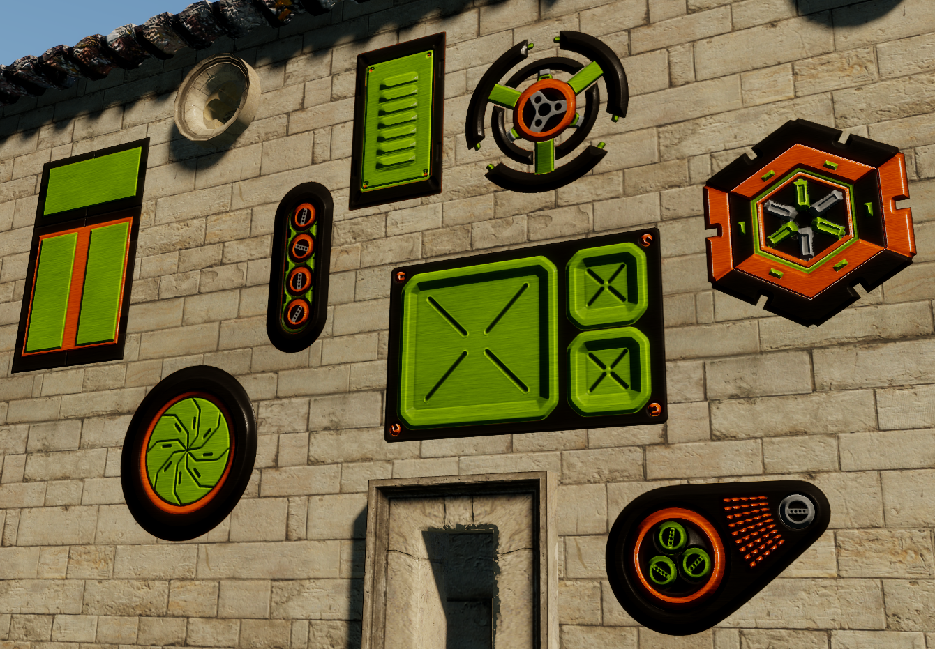
In my demo the decal color and normal are just blended with the surface parameters based on the alpha channel from the color texture. However one advantage of applying decals in this way is that you’re not restricted to framebuffer blending operations. So for instance, you can accumulate surface normals by reorienting the decal normals[19] to make them relative to the normals of the underlying surface.
As for their performance, I unfortunately don’t have another decal implementation to compare against. However if I set up test case where most of the screen is covered in around 11 decals, the cost of the deferred pass (no MSAA) goes from 1.50ms to 2.00ms on my GTX 970. If I branch over the decals entirely (including reading from the cluster bitfield buffer), then the cost drops to 1.33ms. For the forward path it costs about 1.55ms with no decals, 2.20ms with decals, and 1.38 branching over the entire decal step.
Performance
To measure performance, I captured GPU timing information via timestamp queries. All measurements were taken from the default camera position, at 1920x1080 resolution. The test scene is the CryTek Sponza (we really need a new test scene!) with 20 hand-placed spotlights, each casting a 1024x1024 shadow map. There’s also a directional light for the sun that uses 4 2048x2048 shadow cascades. The scene uses normal, albedo, roughness, and metallic maps courtesy of Alexandre Pestana[16]. Here’s what the frame breakdown looks like for the deferred texturing path, with no MSAA:
Render Total: 7.40ms (7.47ms max)
Cluster Update: 0.08ms (0.08ms max)
Sun Shadow Map Rendering: 1.30ms (1.34ms max)
Spot Light Shadow Map Rendering: 1.04ms (1.04ms max)
G-Buffer Rendering: 0.67ms (0.67ms max)
Deferred Rendering: 3.54ms (3.58ms max)
Post Processing: 0.59ms (0.60ms max)
…and here’s what it looks like with 4x MSAA:
Render Total: 9.86ms (9.97ms max)
Cluster Update: 0.08ms (0.08ms max)
Sun Shadow Map Rendering: 1.30ms (1.34ms max)
Spot Light Shadow Map Rendering: 1.04ms (1.05ms max)
G-Buffer Rendering: 1.48ms (1.49ms max)
Deferred Rendering: 4.64ms (4.67ms max)
Post Processing: 0.56ms (0.57ms max)
MSAA Mask: 0.16ms (0.16ms max)
MSAA Resolve: 0.21ms (0.21ms max)
The first timing number is an average over the past 64 frames, while the second number is the maximum time from the past 64 frames.
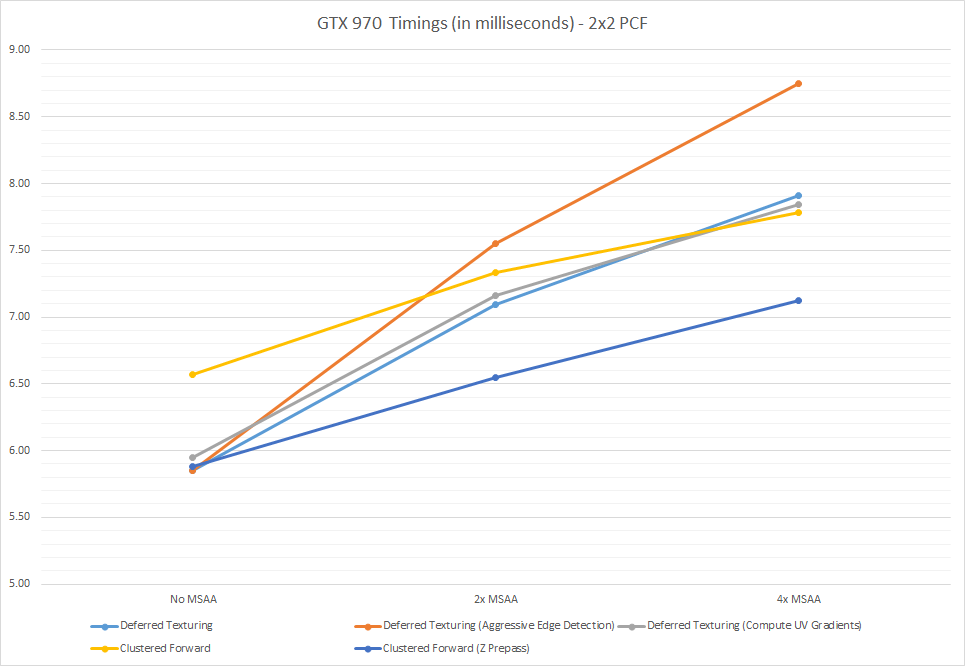
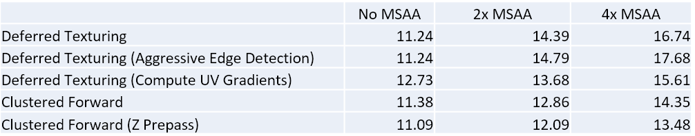
The following chart shows how some of the various configurations scale with increasing MSAA levels:
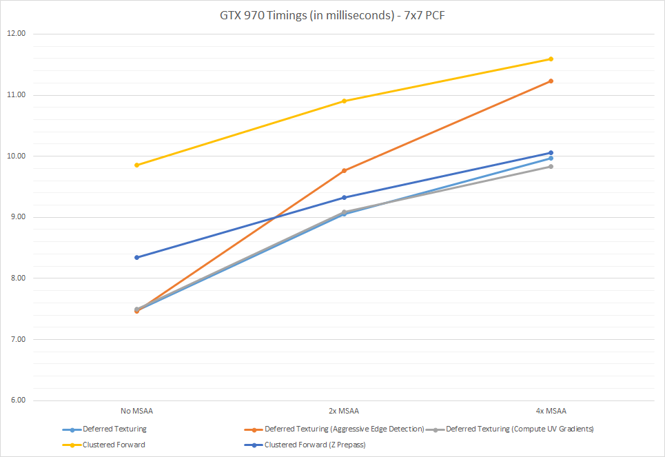
So there’s a few observations that we can make from this data. First of all, the deferred path generally does very well compared to the forward path. The forward path without a depth prepass is basically useless, which means we’re clearly suffering from overdraw problems. I do actually sort by depth when rendering the main forward pass, but my test scene doesn’t have sufficient granularity to achieve good front-to-back ordering. Enabling the depth prepass improves things considerably, but not enough to match the deferred performance. Once we enable MSAA things go a little differently, as the forward paths scale up better compared to the deferred rendering path. At 4x forward and deferred are nearly tied, but that is only when the deferred path uses the conservative material ID check for detecting edge pixels. The conservative path skips many edges in the test scene, and so the AA quality is inferior to the forward path. Using the aggressive depth gradient edge test brings the quality more in line with the forward path, but it’s also quite a bit more expensive. However I would also expect the forward path to scale more poorly with scene complexity, since pixel shader efficiency will only decrease as the triangle count increases. One other interesting observation we can make is that writing out the UV gradients doesn’t seem to be an issue for our test scene when running on my 970. With no MSAA it’s actually slightly faster (7.47ms vs 7.50ms) to just write out the gradients instead of computing them, but that changes by the time we get to 4x MSAA (9.97ms vs. 9.83ms).
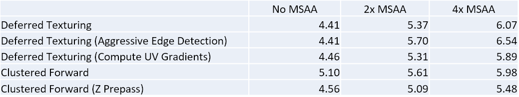
I should point out that all of these timings were captured while using a heavy-duty, “thrash your cache” 7x7 PCF kernel that’s implemented as an unrolled loop using GatherCmp. It undoubtedly causes a large increase in memory traffic, and it probably causes an increase in register pressure as well. I would imagine that this is especially bad for the forward path, since everything is done in one pixel shader. As an alternative, I also have an option to revert back to a simple 2x2 PCF kernel that only uses a single GatherCmp (you can toggle it yourself by changing the “UseGatherPCF_” flag at the top of Shading.hlsl). This path is probably a better representation for games that use filterable shadow maps, and possibly games that use aggressive PCF sampling optimizations. Here’s what the data looks like:
Some of these results are quite different compared to the 7x7 case. The forward paths do much better than they did previously, especially at 4xMSAA. The deferred paths scale the same as they did before, with the aggressive edge detection again causing longer frame times.
At home I only have access to a GTX 970, and so that’s what I used for almost all of my testing, profiling, and optimization. However I was able to verify that the demo works on an an AMD R9 280, as well as a GTX 980. I’ve posted a summary of all of the performance data in table form below (all timings in milliseconds):

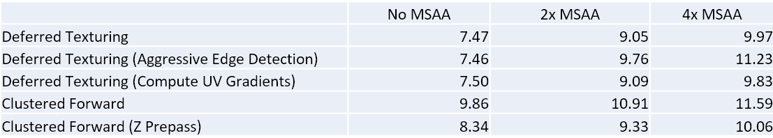

If you’re interested in seeing the raw performance data that includes the per-frame breakdowns, I’ve uploaded them here: https://mynameismjp.files.wordpress.com/2016/03/deferred-texturing-timings.zip. You can also access the timing data in the app by clicking on the “Timings” button in the top-left corner of the screen.
Conclusions and Future Work
So what kind of conclusions can we draw from this experiment? Personally I’m wary of extrapolating too much from such an artificial testing scenario with only one basis for comparison, but I think it’s safe to say that the bindless deferred texturing approach doesn’t have any sort of inherent performance issue that would render it useless for games. Or at least, it doesn’t on the limited hardware that I’ve used for testing. I was initially worried that the combination of SampleGrad and divergent descriptor indices would lead to to suboptimal performance, but in the end it didn’t seem to be an issue for my particular setup. Although to be completely fair, the texture sampling ended up being a relatively small part of the shading process. It’s certainly possible that the situation could change if the number of textures were to increase, or if the indexing became more divergent due to increased material density in screen-space. But at the same time those situations could also lead to reduced performance during a forward pass or during a traditional G-Buffer pass, so it might end up being a wash anyway.
At least in my demo, the biggest performance issue for the deferred path seems to be MSAA. This shouldn’t really be a surprise, considering how hard it is to implement affordable MSAA with any deferred renderer. My hope would be that a deferred texturing approach does a bit better than a traditional deferred renderer with a very large G-Buffer, but unfortunately I don’t have data to prove that out. Ultimately it probably doesn’t even matter, since hardly anyone even bothers with MSAA these days. :(
What about limitations? Multiple UV sets are at best a headache, and at worst a non-option. I think you’d have to really like your artists to store another UV set in your G-Buffer, and also eat the cost of storing or computing another set of UV gradients. Not having a full G-Buffer might be an issue for certain screen-space techniques, like SSAO or screen-space reflections. I’ve shown that it’s possible to have decals even without a full G-Buffer, but it’s more complex and possibly more expensive than traditional deferred decals. But on the upside, it’s really nice to have a cheap geometry pass that doesn’t need to sample any textures! It’s also very friendly to GPU-driven batching techniques, which was demonstrated in the RedLynx presentation from SIGGRAPH.
There is one final reason why you might not want to do this (or at least not right now): it was a real pain in the ass to get this demo working in DX12. Driver bugs, shader compilation bugs, long compile times, validation bugs, driver crashes, blue screens of death: if it was annoying, I ran into it. Dynamic indexing support seems to be rather immature in both the shader compiler and the drivers, so tread carefully. The final code has a few work-arounds implemented, but I’ve noted them with a comment.
Update 8/4/2019: The situation has improved substantially since I wrote this article. Our engine at RAD now makes full use of bindless resources throughout its various rendering passes. Drivers have become much more robust, and the open source shader compiler (DXC) is much faster and more robust compared with FXC (which allowed me to remove some of my workarounds). I’ve also used wave-level intrinsics from SM6.0 to implement scalarization techniques for loading the light/decal data, which forces wave coherency and can substantially reduce VGPR usage on AMD hardware. There is also now a GPU-based validation layer that can validate resources accessed through descriptor indexing, and PIX can now do a similar analysis to show which resources were actually used within a draw or dispatch.
If I were to spend more time on this, I think it would be interesting to explore some of the more extreme variants of deferred texturing. In particular there’s Intel’s paper on Visibility Buffers[17], where the authors completely forego storing any surface data except for triangle ID and instance ID. All surface data is instead reconstructed by transforming vertices during the deferred pass, and performing a ray-triangle intersection to compute barycentrics for interpolation. There’s also Tomasz Stachowiak’s presentation about deferred material rendering[18], where barycentric coordinates are stored in the G-Buffer instead of being reconstructed (which he does by tricking the driver into accepting his hand-written GCN assembly!!!). He has some neat ideas about using tile classification to execute different shader paths based on the material, which is something that could be integrated with the MSAA tile classification that’s performed in my demo. Finally in the RedLynx presentation they use a neat trick where they render with MSAA at half resolution, and then reconstruct full-resolution surface samples during the deferred pass. It makes the deferred shader more complicated, but reduces the pixel shader cost of rasterizing the G-Buffer. These are all things I would love to implement in my demo if I had infinite time, but at some point I actually need to sleep. :)
That’s All, Folks!
If you’ve made it this far, thank you for hanging in there! This one might be my longest so far! I considering making it a series of articles, but I didn’t want it to turn into one of those blog series where the author just never finishes it.
If you want to look at the code or run the sample, everything is available on GitHub:
https://github.com/TheRealMJP/DeferredTexturing
https://github.com/TheRealMJP/DeferredTexturing/releases (Precompiled Binaries)
If you find any bugs or have any suggestions, please let me know via comments, email, GitHub issue, or twitter!
References
[1] Introduction To Resource Binding In D3D12 (Intel)
[2] OpenGL Bindless Extensions (Nvidia)
[3] GL_NV_bindless_texture (OpenGL Extension Registry)
[4] Deferred Texturing (Nathan Reed)
[5] GPU-Driven Rendering Pipelines (Haar and Aaltonen, SIGGRAPH 2015)
[6] Modern Textureless Deferred Rendering Techniques (Beyond3D)
[7] The Bitsquid Low-Level Animation System
[8] Practical Clustered Shading (Emil Persson)
[9] Deferred Rendering for Current and Future Rendering Pipelines (Intel, Andrew Lauritzen)
[10] Forward+: Bringing Deferred Lighting To The Next Level (AMD, Takahiro Harada)
[11] Forward Clustered Shading (Intel)
[12] Correct Frustum Culling (Íñigo Quílez)
[13] Conservative Rasterization (MSDN)
[14] Screen Space Decals in Warhammer 40K: Space Marine (Pope Kim)
[15] Free Sci-Fi Decals 2 (Nobiax, DeviantArt)
[16] Base color, Roughness and Metallic textures for Sponza (Alexandre Pestana)
[17] The Visibility Buffer: A Cache-Friendly Approach to Deferred Shading (Burns and Hunt, JCGT)
[18] A Deferred Material Rendering System (Tomasz Stachowiak)
[19] Blending In Detail (Barré-Brisebois and Hill)
Comments:
Thank you, as always, for sharing your ideas and tests so liberally, it has been very inspiring on many occasions. One thing this all made me think about is the recent interest in distance fields. The idea of using a scene approximation distance field for reflections is enticing to me, as I am mostly interested in depicting relatively small scenes as realistically as possible. Would you happen to have any ideas on rendering via a distance field, finding the intersection and using that (eventually) to fetch textures, materials, shaders, &c? The deferred material rendering article made me think that is not as crazy as it may sound; and it might play nice (seeing all this) with reflections.
#### [Daniel Wright (@EpicShaders)](http://twitter.com/EpicShaders "EpicShaders@twitter.example.com") -
Jeroen, a distance field intersection would only give you world position, so you’d have to use a data structure that can evaluate a material entirely from that, not an easy thing to do efficiently! Plus you really need prefiltered results to solve the cone queries you are doing.
#### [Jeroen D Stout](http://gravatar.com/jeroenstout "jeroenstout@gmail.com") -
Daniel, Hmm, to clarify, my thought was hypothetically you could store the ’nearest’ Mat-ID in the field (if it is a 3d texture) along with a U and a V (admittedly making it a much larger texture). That can get you a world position + UV + mat-ID and come closer to the data for ‘deferred material rendering’. It’s perhaps not very practical.
#### [Ingramb]( "ingramb@gmail.com") -
Any reason why you use buffers rather than 3D textures for cluster storage? Stylistic choice, or are there practical considerations? Really nice article and sample, thanks for sharing.
#### [zbethel](http://zachbethel.wordpress.com "zach.bethel@gmail.com") -
Do you ever sleep? :) This is great work, thanks for sharing. I’m particularly interested in the clustered decal approach, as forward pipelines have traditionally suffered from decal support. It seems like the magic bullet these days is tiled compute approaches! The textureless deferred stuff is interesting, but I’m not sure I’m sold. For one, it still suffers from high memory bandwidth, which means you still end up needing a Z-Prepass. More importantly though, high bandwidth deferred pipelines don’t scale to higher resolutions. We’ve hit a wall with our deferred pipeline in that we simply can’t scale above 1080p and maintain any scene complexity. I’d be interested to run this at a higher resolution and see how the performance compares.
#### [MJP](http://mynameismjp.wordpress.com/ "mpettineo@gmail.com") -
@ingramb: I mainly used a flat buffer so that I could easily vary the maximum number of lights and decals per cluster without having to worry about texture formats. But to be honest I didn’t give it a whole lot of thought. @zbethel: the G-Buffer is definitely still fatter than I’d like it to be. However I’m not sure that you need a depth prepass. I used to have an option to turn on depth prepass for the deferred path, but I disabled it because it was never faster. That might not be the case on hardware with less bandwidth, but either way the G-Buffer pixel shader is *very* cheap. If you want to try it yourself you can re-enable it by uncommenting the code on line 1578 of BindlessDeferred.cpp. I think for lower-end desktop or mobile hardware that’s more bandwidth-constrained, approaches like the Visibility Buffer start to look more appealing due to the ultra-slim G-Buffer. It’s also nice for MSAA, for the same reason. If I run maximized on my 2560x1440 monitor on my GTX 970 I get 10.73ms for deferred, vs. 11.63ms for forward. At 4xMSAA this changes to 14.20ms for deferred (with computing UV gradients enabled), vs. 14.00ms for forward. Using the aggressive edge detection pushes the deferred path up to about 16.00ms.
#### []( "") -
I’d love to use this technique. But I ran into a troubling thought. In a normal deferred shading pipeline, any object that requires some unique shaders to do some fancy work to it’s materials can just output that data to the correct GBuffer. However, how would you do that for deferred texturing? I don’t think you can rebind your programs dynamically from the GPU.
#### [Jason]( "jasonhuang1988@gmail.com") -
Thx a lot, it is this most inspriing article I have ever seen. Btw, would you like to try radiance hints (GI) some day?
#### [MJP](http://mynameismjp.wordpress.com/ "mpettineo@gmail.com") -
Hey Sean, glad you liked the post. I just tried compiling and running the latest code on my GTX 970, and I don’t see either of those issues. Are you on the latest driver? I’m currently running on driver 368.39, which is the latest available.
#### [Sean Dunn](https://www.facebook.com/app_scoped_user_id/10153555138757301/ "seanedunn@yahoo.com") -
This is great stuff, and a very educational post. One problem, though. I’m testing out your demo, and there are some issues I’m having, and wondering if they’re known: 1. Lights flicker terribly in the Clustered Forward render mode, 2. In Deferred Texturing mode, there are many places where the UVs stretch across multiple polygons. These did not show up in your screenshots above, but I’m running on a GTX 970 as well, so I wouldn’t expect to see this. Ex: http://imgur.com/WoXtMjV
#### [Michael]( "segura.mikael@orange.fr") -
Since the forward path is faster using 4xMSAA, is it still better to keep the deferred path ?
#### [Sean Dunn](https://www.facebook.com/app_scoped_user_id/10153555138757301/ "seanedunn@yahoo.com") -
Doh. Turns out this demo is the reason I upgraded to Windows 10, and in my rush, I forgot that my graphics driver would have to be manually updated. Works great now, thanks.
#### [Cull that cone! Improved cone/spotlight visibility tests for tiled and clustered lighting | Bart Wronski](http://bartwronski.com/2017/04/13/cull-that-cone/ "") -
[…] are few solutions to it. I will mention first a heavy / complicated, but best solution, suggested by Matt Pettineo – rasterizing the cone in tested space and then either simply checking against this […]